Unique Self-contained Confocal Laser Scanning Unit
A Unique, Easy-to-use, Self-contained Confocal Laser Scanning Microscope with a Small Footprint
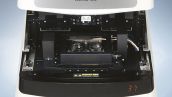
The FV10i features a unique self-contained design. Simplified and optimized, key components, including an incubator and laser combiner, have been integrated into a self-contained package with no compromises. The system, which is easier to set up and use, features the same functionality as a high-end confocal laser scanning microscope while adding vibration isolation and a light tight cover. As a result, the FV10i can be operated by new and experienced users alike and, with a compact footprint, can be installed in any laboratory without the need for a dedicated dark room.
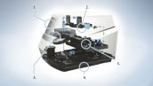
| 1.Dark Room Free | The Microscope body and light tight cover are integrally combined. The FV10i can be used with ease in a laboratory, unlike conventional confocal laser scanning microscopes which may require a dark room. |
|---|---|
| 2.Scanning Unit | The system is equipped with a detector which automatically sets conditions in accordance with fluorescence dye on a scanning unit. Imaging can be performed in the conditions that are most suited for each fluorescence dye. |
| 3.Microscope Function | The FV10i's excellent optical and mechanical modules are totally integrated. The FV10i can capture images from 10× to 600× magnification with 10×, 60× objectives and optical zoom. |
| 4.Vibration Isolation Function | Equipped with built-in vibration insulators. A vibration isolation table is not required and so can be installed directly on an experimental tabletop. |
| 5.Laser Combiner | Equipped with four diode laser units, each unit utilizes a compact diode laser for longer life and power-saving compared to traditional confocal systems. |
High-definition Images using Advanced Optics
Equipped with 4 Diode Lasers
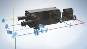
The system is equipped with four (405/473/559/635nm) lasers. Multi-stained specimens can be imaged with up to four fluorescence dyes. Maintenance-free and power-saving diode lasers with longer operating lives are employed in all the laser units, and operate with low noise levels.
Detector Utilizes a Newly Developed Spectrum Method
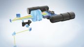
The detecting mechanism has two fluorescence channels, and one phase contrast channel. The fluorescent channels use a newly developed spectrum method comprising grating, beam splitter, and slit. In addition, they are equipped with the variable barrier filter function where the most suitable wavelength width is set automatically in accordance with the characteristics of the fluorescence dye.
Two Sequential Modes
The FV10i is equipped with two sequential modes. Images can be acquired through line sequences without crosstalk in imaging with two fluorescence dyes, and with three or four dyes in frame sequences with the virtual channel function.
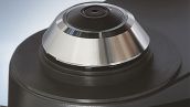
Objectives of 10× and 60× are System-mounted
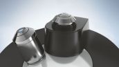
The system is equipped with objectives of 10× and 60×. Zoom magnification can be changed continually from 10× to 600×. The most suitable imaging area can be set depending on the size of the specimen.
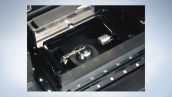
Built-in Incubator Ideal for Time-lapse Imaging
Simplified Built-in Incubator
The system has a simplified built-in incubator, allowing easy time-lapse imaging of live cells without losing valuable time in setting up equipment. The environment in the culture chamber is maintained at a temperature of - 37 degrees Celsius, humidity of - 90 %, and CO2 concentration of - 5 %* . Time-lapse imaging up to a maximum of three days is supported.
* To maintain 5% of CO2 in dish, injection of 6 % CO2 with 150 ml/min is recommended.
A Dedicated Culture Pod is Provided
The system is provided with a dedicated culture pod for dia. 35 mm glass bottom dishes. Recirculation of the culture media and addition of a medicinal solution during time-lapse is possible. In addition, the culture pod system can be autoclaved for sterilization.
Stable Time-lapse Imaging
Not only the incubator but also the surrounding air space is maintained at 37 degrees
Celsius*. Long-term time-lapse imaging is, therefore, possible while maintaining cell activity.
*Fluctuation of ambient temperature may affect focusing stability.
Water is Automatically Supplied to the Water-immersion Objective
The newly developed automatic water dispensing system enables the FV10i to supply water to the top of the water-immersion objective. Long term time-lapse imaging can continue without concern for immersion media levels. Water is supplied automatically when the objective is moved into the observation position.
Detection of Cover Glass Thickness and Automatic Adjustment of the Correction Collar
The system is equipped with the capability to detect the thickness of the cover glass, allowing it to adjust the correction collar automatically, when using the water-immersion objective. This assures imaging is performed each time with optimal conditions.
Supports Multi-area Time-lapse Imaging
The system is equipped with a motorized stage, and imaging is possible through multi-area time-lapse. Ten point locations can be assigned within a single dish (well). For example, in the case of a dia. 35mm glass bottom dish, three dishes can be mounted, allowing a maximum of up to 30 locations to be captured.
Start Capturing Images from the First Day
Stress-free Operation for Every User
Only two manual steps are required of the user: placing of the specimen on the stage and closing the cover. After that, the sophisticated user interface offers clear and efficient operation of the microscope. The selection of the imaging point, for example, can be performed easily using the newly designed image mapping menu without need for special experience or expertise. Furthermore, using advanced functionality that is only found in Olympus products, automatic focus and intensity adjustment allow the imaging conditions to be set up according to the type of specimen and observation mode required. In addition, the system is equipped with a navigation function that identifies the operational step of the imaging procedure and guides the operator to the next appropriate operation. The FV10i confocal laser scanning microscope, therefore, provides a stress-free and comfortable operating environment even for first-time users.
Setting
Place a specimen, and select a fluorescence dye. The FV10i automatically selects the most suitable imaging conditions based on the fluorescence dye selection.
Image Mapping Menu
Just click the <Start> button, and a map image of the specimen is created automatically. Users can then easily identify the desired image acquisition point.
Image Capturing
Through the sophisticated operating software, the image capture area or zoom magnification can be set quickly. Image capture is then completed at the click of a button.
Capture a Map Image Easily for Navigation
When the Specimen Has Been Loaded, Clicking <Start> Begins the Mapping Process
Following the loading of the specimen, a map image can be acquired by simply clicking the <Start> button in the "Acquire Map Image" window. With this bird's-eye view of the specimen, the user can quickly and easily select the imaging area to be captured.
Create Map Area
The map image provides the user with an overview of the possible image capture area. The selectable map areas are automatically displayed in a diagram according to the type of specimen holder that has been used, such as a 35 mm diameter dish or glass slide. An area can be selected and map image acquired by clicking on the desired scan area in the diagram. This will display an overview image of the area on the “Map Image” screen. Selecting an alternative area requires just a single click operation.
Fluorescence Dye Selection
A separate map image can be displayed for each fluorescence dye. These images can be displayed individually or be overlaid with each other.
Scanning Setting
One of two scanning orders can be selected depending on the experimental requirements.
Automatic
A map image is automatically acquired from the center outward in a spiral pattern, allowing even a first-time user to easily identify the confocal view area.
Manual
The desired map image areas can be selected directly up to a maximum 9 × 9 area. Manual selection is more efficient than automatic selection as the ROI (Region of Interest) can be narrowed down in advance.
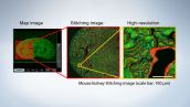
A Map Image of the Specimen Can be Automatically Created
A map image can be created by automatically detecting which type of specimen holder is used. High speed with low resolution or low speed with high resolution image mapping options is available.
Easy Guided Operation for First-time Users
Sophisticated Menus Allow Easy Navigation of Imaging Area
The desired imaging region can be selected using the map image and live image screens utilizing the zooming function of the intuitive user interface. The user friendly navigation functions allow even a first-time user to capture images with ease.
| Observation Mode Selection |
Five types of observation modes can be selected including time-lapse, Z-stack, and multi-area
|
|---|---|
| Multi-area Setting | Register the areas for imaging in multi-area mode. Appropriate imaging conditions can be set for each area. |
| Map Image | The image acquired in [Acquire Map Image] is displayed. Specific regions can be selected for closer examination. |
| Control Screen | Imaging conditions can be set in detail with operation of various controllers. Main settings include:
|
| Live Image | The selected point from the map image screen is displayed. The imaging area is determined through the framing and zooming functions. It is possible here to switch between the displays for each type of fluorescence dye. |
The System is Equipped with a User Friendly Navigation Function

Clicking the <Navigation> button shows the operational procedure and highlights the operational button. Just follow the navigational guidance to easily complete your imaging.
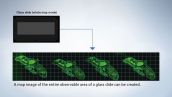
Stitching Function
Wide-angle high-resolution imaging can be obtained by acquiring the adjacent regions. A map image of the entire glass slide can also be created.
Software ZDC Function (FV10i-LIV Only)
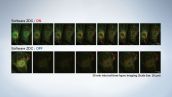
Z-drift compensation function (software ZDC) reduces Z-drift by temperature-shift in time-lapse imaging.
Dedicated Analysis Software Exclusive to FLUOVIEW
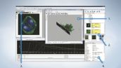
Dedicated Olympus software is provided as part of the standard specifications, bringing editing and analysis capabilities to images taken by FV10i.
| 3D Display Function(No.1) | The FV10i supports the Alpha Blend method and Maximum Intensity Projection method for the 3D display function. Also, the system is equipped with various display functions which allow a user to freely change the angle of 3D images and section the image at any spot. | ||||||||
|---|---|---|---|---|---|---|---|---|---|
| Easy Image Searching(No.2) | Thumbnail list is possible on the main screen allowing a user to easily search for previous image data. | ||||||||
| 2D Analysis Tool(No.3) |
| ||||||||
| Data Manager(No.4) | The data manager displays thumbnails and various file information with clarity. |
File Input/Output
OIF (Olympus Image Format) is employed to store various parameter settings and images together. This software supports a wide range of well-used formats with high interchangeability including TIFF, BMP and JPEG.
Feature-rich Functionality for Stress-free Imaging
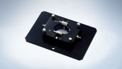
Equipped with various Specimen Holders

The system is equipped with specimen holders, usable for a dia. 35 mm glass bottom dishes, glass slides, cover glass chambers (8 wells type), and well slides (8 wells type). Specimens can be observed without the risk of contamination using the closed contamination-free plastic cover of a dia. 35 mm glass bottom dish.
Capturing Adjacent Images in Wide field
Imaging of adjacent images is possible to create big mosaic images. These can be captured in high-definition and wide field of view.
HDD Recording for Storing Large Volumes of Data
The microscope comes equipped with a HDD (hard-disk drive) recording function. The images captured are stored automatically in the HDD. Large volumes of data, such as those obtained from long-term time-lapse imaging can be stored. During imaging, editing/analysis of previously taken images is also possible. An external HDD connected to a network can be specified as the destination, and the saved images can be viewed on a remote PC while performing separate imaging.