While microscopes and other imaging devices have traditionally been large, modern design techniques are leading to more compact systems. However, the miniaturization of these systems raises an important question: how do you lay out an optical system in a compact device?
As a leading provider of optical components for the life science, medicine, and industrial fields, this question often comes up in our discussions with manufacturers of microscope-based imaging devices. Here, we provide a few ideas on how to minimize an optical system for a compact device.
Key Considerations for Designing a Compact Optical System
An optical system that extends from a microscope objective to a camera’s imaging surface (imaging optical system) consists of three units:
- An objective, which is placed close to the specimen
- A tube lens, which focuses the flux of light from the objective
- A camera adapter, which projects images onto a camera at an appropriate magnification
It’s important to select and combine the appropriate units from the various options according to the device's purpose. Here are some factors to consider for each component:
1. Objectives
We provide more than 100 types of UIS2 objectives, including the X Line series, which offers high performance levels for three important elements of an objective: numerical aperture, chromatic aberration correction, and image flatness. These objectives also have a parfocal distance of 45 mm, are compensation free, and have a small physical footprint. Our X Line objectives, along with some of our other objectives, support wavefront aberration control.
Use our Objective Finder to filter the objectives according to your most important parameters (e.g., numerical aperture, magnification, use of a cover glass, oil immersion, and color aberration). This handy online tool helps you compare their performance to select the best option.
2. Tube lens
Five types of tube lenses are available, as listed in Table 1 below. All units are compensation free. The U-SWATLU produces a 26.5 mm image circle to cover a super wide field of view, so we recommend that it is combined with an X Line objective.
| Product name | Image circle | Total length | Max. outer diameter | Weight | Mounting thread |
|---|---|---|---|---|---|
| U-SWATLU | 26.5 mm | 77.8 mm | 60 mm | 460 g | Circular dovetail (proprietary Olympus method) |
| U-TLU | 22 mm | 63.6 mm | 60 mm | 350 g | |
| U-TLUIR | 22 mm | 63.6 mm | 60 mm | 350 g | |
| SWTLU-C | 26.5 mm | 33.6 mm | 45 mm | 94 g | Engagement (φ 39) and screw-in (M41 × 0.5 mm) |
| TLU-C | 22 mm | 20 mm | 38 mm | 40 g | Engagement (φ 34) and screw-in (M36 × 0.5 mm) |
Table 1. Specifications of the tube lenses
3. Camera adapter
We provide four types of camera adapters with different projection magnifications: the U-TV1XC, the U-TV0.63XC, the U-TV0.5XC-3, and the U-TV0.35XC-2. Please select the field of view that you need based on the sensor size of the image pickup device for your camera.
Producing Compact Imaging Devices for Large Fields of View at Low Magnification
In the life science field, there has been an increased demand to produce compact imaging devices that enable wide fields of view with observations at low magnification.
In light of this, let’s consider how the length of an imaging optical system can be minimized by using the UPLXAPO4X, a typical low-magnification objective in the X Line series. This process can be done in four steps:
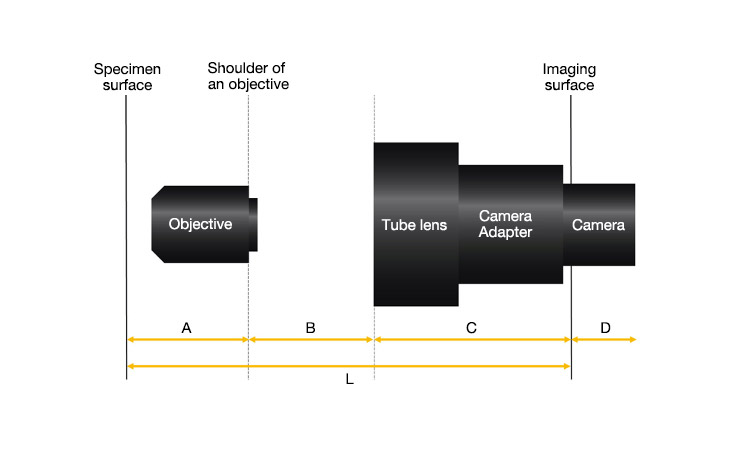
Figure 1: Basic layout of an optical system
1. Determine the field of view
The value obtained by dividing the objective’s field number (OFN) by its magnification is the maximum range that can be viewed on the specimen surface. Because the OFN of the UPLXAPO4X is 26.5, the range that can be viewed on the specimen surface can be calculated as: 26.5 / 4 = ø 6.625 mm. Our UIS2 objectives are designed to have a parfocal distance of 45 mm (distance A).
2. Select a tube lens
Our UPLXAPO4X objective has an OFN of 26.5, and it can be combined with a tube lens that produces a 26.5 mm image circle to take full advantage of its performance. Accordingly, we recommend you combine the U-SWATLU tube lens with an X Line objective. This combination enables you to obtain images that are clear and homogeneous, even at the center of or around the image pickup device.
3. Select a camera adapter
Next, select a camera adapter. As shown in Table 2, the distance to the imaging surface (distance C) can be shortened by using the different reduction ratios of various camera adapters. The length of an optical system can be minimized by combining the tube lens with a camera adapter that has a 0.35X magnification.
|
U-TV1XC
1x |
U-TV0.63XC
0.63x |
U-TV0.5XC-3
0.5x |
U-TV0.35X-2
0.35x | |
|---|---|---|---|---|
| U-SWATLU | 174 mm | 154 mm | 122 mm | 107 mm |
| U-TLU (IR) | 160 mm | 139 mm | 108 mm | 93 mm |
Table 2: Distance C for tube lenses combined with different camera adapters
It is important to select an adapter magnification so that the value obtained by dividing the camera sensor’s diagonal width by the adapter’s magnification won’t exceed the image circle of the tube lens.
For example, let’s say you select a camera adapter with a 0.35X magnification due to the restricted total length of the imaging optical system and combine it with a 1/1.8-inch camera (with a diagonal width of 9 mm). In this case, you need to divide 9 by 0.35 to find the value for comparison (25.7):
22 < 9 / 0.35 = 25.7 < 26.5
So, the U-SWATLU (rather than the U-TLU) should be selected as the tube lens.
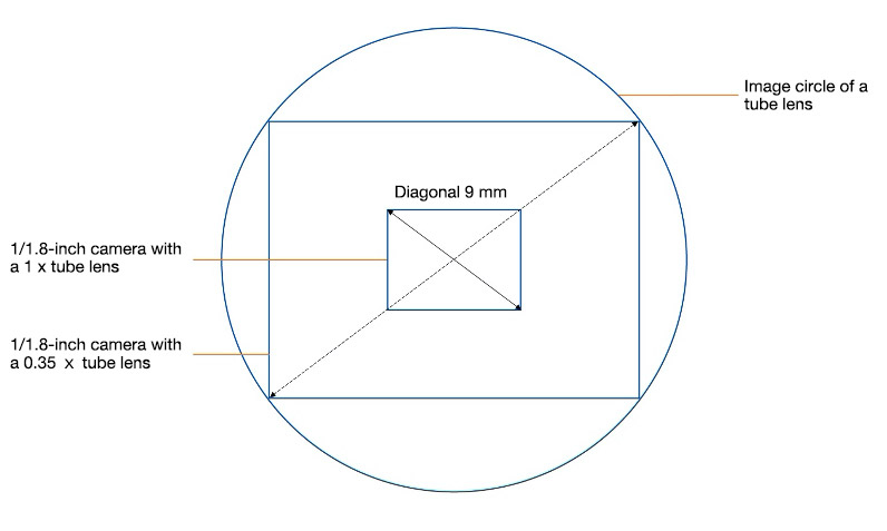
Figure 2: Camera sensor size and image circle for the tube lens
4. Determine distance B
In steps 1 to 3, we selected the units required for the imaging optical system. After that, all you need to do is determine distance B as the final parameter.
Since all UIS2 objectives are infinity-corrected optical systems that are compensation free, you can change distance B to suit your needs.
We recommend that the length of B is between 65 mm and 170 mm when using the U-SWATLU tube lens. In this example, we selected 65 mm as the length of B to build a compact device. But you can select another length depending on your desired layout. For example, you can extend the distance to insert an optical system for reflected illumination.
Final Thoughts about Designing Compact Optical Systems
Following steps 1 to 4, you can build an imaging optical system with a total length of 217 mm (Figure 3). Properly combining our UIS2 objectives, tube lenses, and camera adapters enables you to design short optical systems for compact devices.
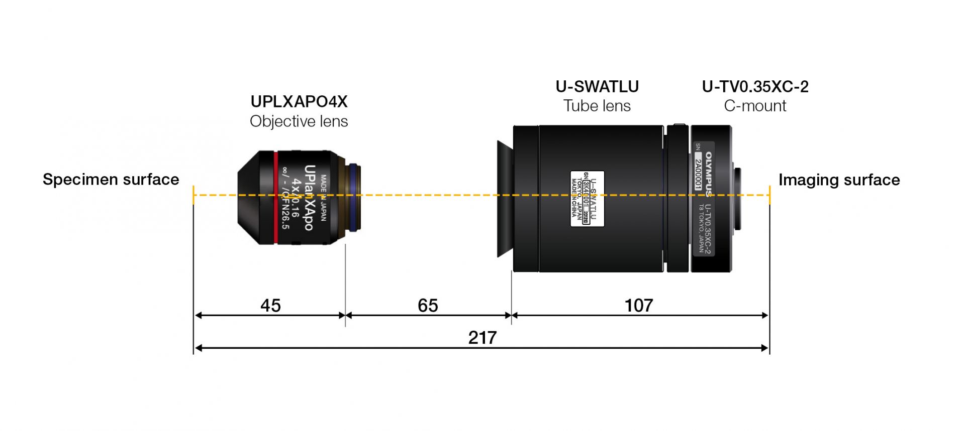
Figure 3: Illustration of a compact imaging optical system with a total length of 217 mm
One factor that’s often overlooked is the camera size (distance D in Figure 1). High-sensitivity cameras generally have a cooling device, so they tend to be large. Make sure to consider the camera size when you set the optical system’s total length (L).
Editor’s note: This post was originally published in March 2021 and has been updated with the latest specifications.
Related Content
The Importance of Compensation-Free Optics in Microscope Design
Why Objectives with Wavefront Aberration Control Are Essential for Good Microscope Design
Good Optics—Improving Single-Molecule Sensitivity in Confocal Microscopy