Lens errors in modern optical microscopy are an unfortunate problem caused by artifacts arising from the interaction of light with glass lenses. There are two primary causes of non-ideal lens action: Geometrical or Spherical aberrations are related to the spherical nature of the lens and approximations used to obtain the Gaussian lens equation; and Chromatic aberrations, which arise from variations in the refractive indices of the wide range of frequencies found in visible light.
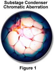
In general, the effects of optical aberrations are to induce faults in the features of an image being observed through a microscope. Chromatic aberration in the substage condenser is illustrated in Figure 1, where blue fringing at the edge of the field diaphragm image is due to chromatic aberration. These artifacts were first addressed in the eighteenth century when physicist John Dollond discovered that chromatic aberrations would be reduced or corrected by using a combination of two different types of glass in the fabrication of lenses. Later, during the nineteenth century, achromatic objectives with high numerical aperture were developed, although there were still geometrical problems with the lenses. Modern glass formulations and antireflective coatings coupled to advanced grinding and manufacturing techniques have all but eliminated most aberrations from today's microscope objectives, although careful attention must still be paid to these effects, especially when conducting quantitative high-magnification video microscopy and photomicrography.
Spherical Aberration - These artifacts occur when light waves passing through the periphery of a lens are not brought into focus with those passing through the center as illustrated in Figure 2. Waves passing near the center of the lens are refracted only slightly, whereas waves passing near the periphery are refracted to a greater degree resulting in the production of different focal points along the optical axis. This is one of the most serious resolution artifacts because the image of the specimen is spread out rather than being in sharp focus.
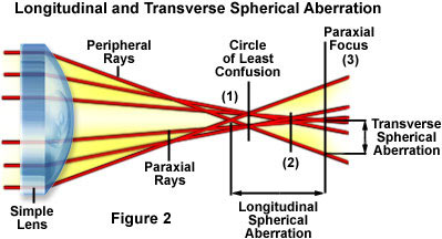
Figure 2 illustrates an exaggerated view of three hypothetical monochromatic light rays passing through a convex lens. Refraction of the peripheral rays is greatest followed by those in the middle and then the rays in the center. The larger refraction by the outermost rays results in a focal point (drawn as focal point 1) that occurs in front of the focal points produced by rays passing closer to the center of the lens (focal points 2 and 3). Most of this discrepancy in focal points arises from approximations of the equivalency of sine and tangent values of respective angles made to the Gaussian lens equation for a spherical refracting surface:
where n and n' represent the refractive index of air and the glass comprising the lens, respectively, s and s' are the object and image distance, and r is the radius of curvature of the lens. This expression determines the relative locations of images formed by the curved surface of a lens having radius r sandwiched between media of refractive indices n and n'. A refinement of this equation is often referred to as a higher-order (first, second, or third) correction by including terms in the cube of the aperture angle resulting in a more refined calculation.
Spherical aberrations are very important in terms of the resolution of the lens because they affect the coincident imaging of points along the optical axis and degrade the performance of the lens, which will seriously affect specimen sharpness and clarity. These lens defects can be reduced by limiting the outer edges of the lens from exposure to light using diaphragms and also by utilizing aspherical lens surfaces within the system. The highest-quality modern microscope objectives address spherical aberrations in a number of ways including special lens-grinding techniques, improved glass formulations, and better control of optical pathways.
Chromatic Aberrations - This type of optical defect is a result of the fact that white light is composed of numerous wavelengths. When white light passes through a convex lens, the component wavelengths are refracted according to their frequency. Blue light is refracted to the greatest extent followed by green and red light, a phenomenon commonly referred to as dispersion. The inability of the lens to bring all of the colors into a common focus results in a slightly different image size and focal point for each predominant wavelength group. This leads to colored fringes surrounding the image as illustrated in Figure 3 below:
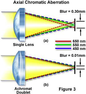
where we have greatly exaggerated the differences in the refractive properties of white light component wavelengths. This is described as the dispersion of the refractive indices of the components of white light. Refractive index is the ratio of the speed of light in a vacuum as compared to its speed in a medium such as glass. For all practical purposes, the speed of light in air is virtually identical to the speed of light in a vacuum. As can be seen in Figure 3, each wavelength forms its own independent focal point on the optical axis of the lens, an effect called axial or longitudinal chromatic aberration. The net result of this lens error is that the image of a point, in white light, is ringed with color. For example, if you were to focus at the "blue plane", the image point would be ringed with light of other colors, with red on the outside of the ring. Similarly, if you were to focus a point at the "red plane", the image point would be ringed with green and blue.
Chromatic aberration is very common with single thin lenses produced using the classical lens-maker's formula that relates the specimen and image distances for paraxial rays. For a single thin lens fabricated with a material having refractive index n and radii of curvature r(1) and r(2), we can write the following equation:
where s and s' are defined as the object and image distance, respectively. In the case of a spherical lens, the focal length (f) is defined as the image distance for parallel incoming rays:
The focal length f varies with the wavelength of light as illustrated in Figure 3. This variation can be partially corrected by using two lenses with different optical properties that are cemented together. Lens corrections were first attempted in the latter part of the 18th century when Dollond, Lister and others devised ways to reduce longitudinal chromatic aberration. By combining crown glass and flint glass (each type has a different dispersion of refractive index), they succeeded in bringing the blue rays and the red rays to a common focus, near but not identical with the green rays. This combination is termed a lens doublet where each lens has a different refractive index and dispersive properties. Lens doublets are also known as achromatic lenses or achromats for short, derived from the Greek terms "a" meaning without and "chroma" meaning color. This simple form of correction allows the image points at 486 nanometers in the blue region and 656 nanometers in the red region to now coincide. This is the most widely used lens and is commonly found on laboratory microscopes. Objectives which do not carry a special inscription stating otherwise are likely to be achromats. Achromats are satisfactory objectives for routine laboratory use, but since they are not corrected for all colors, a colorless specimen detail is likely to show, in white light, a pale green color at best focus (the so-called secondary spectrum). A simple achromat lens is illustrated in Figure 4 below.
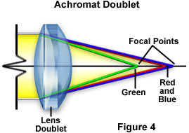
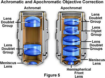
As can be seen in this figure, the proper combination of lens thickness, curvature, refractive index, and dispersion allows the doublet to reduce chromatic aberration by bringing two of the wavelength groups into a common focal plane. If fluorspar is introduced into the glass formulation used to fabricate the lens, then the three colors red, green, and blue can be brought into a single focal point resulting in a negligible amount of chromatic aberration. These lenses are known as apochromatic lenses and they are used to build very high-quality chromatic aberration-free microscope objectives. Modern microscopes utilize this concept and today it is common to find optical lens triplets (Figure 5) made with three lens elements cemented together, especially in the higher-quality objectives. For chromatic aberration correction, a typical 10x achromat microscope objective is built with two lens doublets, as illustrated in Figure 5, on the left. The apochromat objective illustrated on the right in Figure 5 contains two lens doublets and a lens triplet for advanced correction of both chromatic and spherical aberrations.
The famous German lens maker Ernst Abbe was the first to succeed in making apochromatic objectives in the late 19th century. Since Abbe, for design reasons at the time, did not accomplish all chromatic correction in the objectives themselves, he chose to complete some of the correction via the eyepiece; hence the term compensating eyepieces.
In addition to longitudinal (or axial) chromatic aberration correction, microscope objectives also exhibit another chromatic defect. Even when all three main colors are brought to identical focal planes axially (as in fluorite and apochromat objectives), the point images of details near the periphery of the field of view are not the same size. This occurs because off-axis ray fluxes are dispersed, causing the component wavelengths to form images at different heights on the image plane. For example, the blue image of a detail is slightly larger than the green image or the red image in white light, resulting in color ringing of specimen details at the outer regions of the field of view. Thus, the dependence of axial focal length on wavelength produces a dependence of the transverse magnification on wavelength as well. This defect is known as lateral chromatic aberration or chromatic difference of magnification. When illuminated with white light, a lens with lateral chromatic aberration will produce a series of overlapping images varying in both size and color.
In microscopes having a finite tube length, it is the compensating eyepiece, with chromatic difference of magnification just the opposite of that of the objective, which is utilized to correct for lateral chromatic aberration. Because this defect is also found in higher magnification achromats, compensating eyepieces are frequently used for such objectives, too. Indeed, many manufacturers design their achromats with a standard lateral chromatic error and use compensating eyepieces for all their objectives. Such eyepieces often carry the inscription K or C or Compens. As a result, compensating eyepieces have built-in lateral chromatic error and are not, in themselves, perfectly corrected. In 1976, Nikon introduced CF optics, which correct for lateral chromatic aberration without assistance from the eyepiece. Newer infinity-corrected microscopes deal with this issue by introducing a fixed amount of lateral chromatic aberration into the tube lens used to form the intermediate image with light emanating from the objective.
It is interesting to note that the human eye has a substantial amount of chromatic aberration. Fortunately, we are able to compensate for this artifact when the brain processes images, but it is possible to demonstrate the aberration using a small purple dot on a piece of paper. When held close to the eye, the purple dot will appear blue at the center surrounded by a red halo. As the paper is moved farther away, the dot will appear red surrounded by a blue halo.
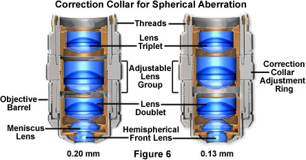
Although microscope manufacturers expend a considerable amount of resources to produce objectives free of spherical aberration, it is possible for the user to inadvertently introduce this artifact into a well-corrected optical system. By utilizing the wrong mounting medium (such as live tissue or cells in aqueous environments) with an oil immersion objective or by introducing similar refractive index mismatches, microscopists can often produce spherical aberration artifacts in an otherwise healthy microscope. Also, when using high magnification, high numerical aperture dry objectives, the correct thickness of the cover glass (suggested 0.17 mm) is critical; hence the inclusion of a correction collar on such objectives to enable adjustment for incorrect cover glass thickness as shown in Figure 6 below. The objective on the left has been adjusted for a cover glass thickness of 0.20mm by bringing the lens elements of the correction collar closer together. By moving the lens elements far apart on the other extreme (the objective on the right in Figure 6), the objective is corrected for a cover glass thickness of 0.13mm. Similarly, the insertion of accessories in the light path of finite tube length objectives may introduce aberrations when the specimen is refocused, unless such accessories have been properly designed with additional optics. We have built an interactive Java tutorial designed to familiarize our readers with objective correction collars for coverslip thickness variations.
Different quality objectives differ in how well they bring the various colors to common focus and same size across the field of view. Between the achromatic and apochromatic type correction, there are also objectives known as semi-apochromats or, rather confusingly, as fluorites. The fluorites cost less but are almost as well-corrected as the apochromats; as a result, they are usually also well-suited for photomicrography in white light.
Coverslip Thickness Correction
Explore how a microscope objective can be adjusted to correct for coverslip thickness variations.
Other Geometrical Aberrations - These include a variety of effects including astigmatism, field curvature, and comatic aberrations that are easily corrected with proper lens fabrication. The topic of field curvature has already been discussed in detail in a previous section. Comatic aberrations are similar to spherical aberrations, but they are only encountered with off-axis objects and are most severe when the microscope is out of alignment. In this instance, the image of a point is asymmetrical, resulting in a comet-like (hence, the term coma) shape. Coma is often considered the most problematic aberration due to the asymmetry it produces in images. It is also one of the easiest aberrations to demonstrate. On a bright, sunny day, use a magnifying glass to focus an image of the sun on the sidewalk and slightly tilt the glass with respect to the principal rays from the sun. The sun's image, when projected onto the concrete, will then elongate into a comet-like shape that is characteristic of comatic aberration.
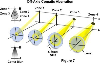
The distinct shape displayed by images with comatic aberration is a result of refraction differences by light rays passing through the various lens zones as the incident angle increases. The severity of comatic aberration is a function of thin lens shape, which in the extreme, causes meridional rays passing through the periphery of the lens to arrive at the image plane closer to the axis than do rays passing nearer the axis and closer to the principal ray (see Figure 7). In this case the peripheral rays produce the smallest image and the coma aberration sign is said to be negative. In contrast, when the peripheral rays are focused further down the axis and produce a much larger image, the aberration is termed positive. The "comet" shape may have its "tail" pointing toward the center of the field of view or away depending upon whether the comatic aberration has a positive or negative value.
Comatic aberrations are usually corrected with spherical aberrations or by designing lens elements of various shapes to eliminate this error. Objectives that are designed to yield excellent images for wide field-of-view eyepieces, have to be corrected for coma and astigmatism using a specially-designed multi-element optic in the tube lens to avoid these artifacts at the periphery of the field of view.
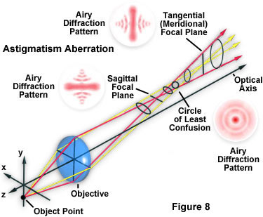
Astigmatism aberrations are similar to comatic aberrations, however these artifacts are not as sensitive to aperture size and depend more strongly on the oblique angle of the light beam. The aberration is manifested by the off-axis image of a specimen point appearing as a line or ellipse instead of a point. Depending on the angle of the off-axis rays entering the lens, the line image may be oriented in either of two different directions (Figure 8), tangentially (meridionally) or sagittally (equatorially). The intensity ratio of the unit image will diminish, with definition, detail, and contrast being lost as the distance from the center is increased.
Astigmatism errors are usually corrected by design of the objectives to provide precise spacing of individual lens elements as well as appropriate lens shapes and indices of refraction. The correction of astigmatism is often accomplished in conjunction with the correction of field curvature aberrations.
From our discussion on optical aberrations, it should be clear that there are a number of factors that influence the performance of optical elements within the microscope. While there has been tremendous progress in the correction of these artifacts in recent years, designers still find it very difficult to completely remove or suppress all of the complicating optical problems associated with microscopy.