Successful photography through the microscope requires careful attention not only to microscope and camera configuration, but also to film exposure and processing parameters. Color negative film has a much wider exposure latitude than does transparency (slide) film, with the added bonus that color balance problems and undesirable color casts and shifts can often be corrected during printing.

A number of factors adversely affect image quality when using color negative films, including improper illumination, misalignment of microscope optics, dirt on or near a conjugate image plane surface, vibration, use of the wrong filters, and improper handling of film. Use the guide below to troubleshoot common photomicrography errors that occur when using color negative film.
The specimen employed in this discussion is a brightfield photomicrograph of a quadruple stained thin section of pine tree stem infected with White Pine Blister Rust, a serious disease of pine trees caused by the fungus Cronartium ribicola. The stain mixture consists of safranin O (nuclei and chromosomes and cell walls), fast green (cytoplasm and cellulose cell walls), crystal violet (starch), and orange G (acidophilic cytoplasm). This photomicrograph was chosen because of the bright reds and greenish blue hues generated by the stain and their rapid identification in color negatives.
Evaluation of color negatives is somewhat difficult and requires more skill and experience than do black & white negatives or color transparencies. Highlight areas should not be excessively dense and shadowed features should be sufficiently detailed to render an overall balanced photomicrograph. Judging specific colors in color negatives is complicated by the presence of a mask that produces an orange tint over both the sprocket holes and the image area, including the color dye layers. The purpose of this mask is to help control contrast and correct for deficiencies in green and red-sensitive layers when the negatives are printed.
Another hurdle to judging tonal quality in color negatives arises because only complementary colors are visible on the film, not the actual colors of the specimen photographed through the microscope. For example, red hues appear as cyan on the negative film and, in a similar manner, green and blue colors in the final print are magenta and yellow on the negatives. The basic confusion of evaluating color definition by examining complementary colors is complicated by the fact that mixed colors and pastels are even harder to interpret. As a result, the real colors present on color negative film can only be evaluated to the fullest extent by making a test print from the film.
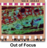 Out of Focus - Improper focus or blurry images are the largest source of errors in photomicrography. In many cases it is difficult to determine whether a photomicrograph that is not properly focused was the result of vibration in the microscope stand or simply due to improper adjustment of the focal distance between the optics and film plane. When the image appears in sharp focus through the oculars, but resulting photomicrographs are blurred, it is a good indication that the film plane and viewing optics may not be parfocal. This error often occurs with low power (1x - 4x) objectives where the film plane depth of focus is very shallow. Carefully adjust focus between the ocular and the focus finder to ensure they are parfocal to the film. The reticles in both the ocular and focus finder should be simultaneously in sharp focus, and the interpupillary distance between oculars should be properly maintained. Adjust both oculars so they are parfocal with each other and the focus finder. Also check the projection lens or phototube eyepiece to ensure it is seated firmly.
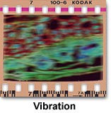 Intermittent focus errors often occur due to vibration, and usually are seen most often when high magnification objectives are used. Test for vibration problems by focusing the microscope on a specimen having sharp edge definition and using the highest magnification objective possible. Vibrations from the table or wind currents from air-handling units will cause the microscope to slowly lose focus. Allow the microscope to remain stationary while focused on the specimen and measure the time required for vibrations to bring the microscope out of focus. If the focus drop occurs immediately, some form of vibration isolation is necessary. However, if the microscope will stay in focus at high magnification for several minutes or longer, then vibration levels are sufficiently low enough for most photomicrography. Stage drift is a problem that occurs when the weight of the stage induces movement in the microscope focus rack, lowering the stage (and specimen) and causing the microscope to lose focus. In many modern microscopes, a focus rack tensioning mechanism is included to eliminate or reduce drift. Some vibration problems are caused by mechanical shutter actions in camera attachments. Always use a cable release with cameras having a mechanical shutter and increase exposure time with neutral density filters if vibration problems persist.
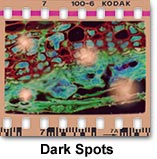 Dark Spots and Debris - Dirt, dark spots, and debris that appear on photomicrographs are common sources of problems with photomicrography, and may occur either in focus with the image or as a blurred spot on the film. If the debris appears in sharp focus, then it is usually occurring from contamination of a lens surface residing in or near a plane conjugate to the focused specimen. The field lens and any glass adjacent to the microscope field diaphragm are often prone to collecting dirt, and these components lie near one of the principal image conjugate planes. Contamination near the field diaphragm will appear in sharp focus on film, and scratches or dirt on filters placed near the field diaphragm are often a source of haze and debris artifacts. Glass surfaces that have been scratched will appear as unsharp areas on photomicrographs, as will bubbles embedded in the lamp condenser glass or in heat-absorbing filters. Often these bubbles will have a bluish tinge when recorded on film. Contamination of the diffusion screen surface with dust and debris or imperfections within the glass of the screen (bubbles) result in pink or blue spots on photomicrographs.
Another common source of dirt and debris is the specimen itself, which also resides in a conjugate plane. Dust adhering to the surface of the coverslip will appear as unfocused dark spots on the film, while contamination on the specimen itself will usually appear as debris that is in focus with the specimen. Dust and debris on a lens near the intermediate image plane is not common, but can sometimes occur. This plane is positioned at the fixed diaphragm of the eyepiece, which can become contaminated when the eyepiece is removed from the microscope and the lens nearest the fixed diaphragm becomes dirty.
When viewing contamination through the microscope eyepieces and attempting to locate the source, slowly turn each eyepiece individually to determine if the debris spots rotate with one of the eyepieces. If so, then the contamination resides on the eyepieces themselves. Rotate other components in the microscope optical pathway, such as filters, the projection lens, the camera system, and the condenser when trying to locate the source of dust and debris. In some instances, it is helpful to capture photomicrographs for the purposes of constructing a record as the components are being rotated. Also translate the specimen back and forth while observing through the eyepieces to determine if debris moves with the specimen. Finally, swing the objective and condenser top lens into and out of the light path and examine whether contaminating debris shifts with either the objective or condenser.
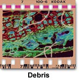 Occasionally, fibers and lint may become wedged between leaves in the field diaphragm or caught in the film carrier inside the camera or black box. When this occurs, the debris will appear in sharp focus (see illustration). This type of contamination is more difficult to diagnose and may present some problems with removal. If there is debris in the field diaphragm, an experienced repair engineer should be employed for microscope cleaning. Debris in the camera back can be removed with compressed air or a camel hair brush. Cleaning dirt and debris from lenses, filters, and the specimen slide should be carefully done with lens tissue or a soft cotton swab. Remove any loose dirt with a can of compressed air or camel's hair brush.
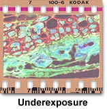 Underexposure - When the film does not receive enough light to properly expose the emulsion, an underexposure error occurs and the resulting color negative will appear too light. Underexposed film typically leaves shadowed areas too dark and lacking in detail and highlight areas are usually rendered in shades of yellow and gray. Color and Black & White negative films display a substantially greater degree of exposure latitude than do color transparency films, primarily because many exposure errors can be corrected during printing. Overexposure is tolerated by negative films much better than underexposure and leads to better prints, although the proper exposure will always produce superior results. Typically in a microscope, the average specimen brightness may not be uniform over the entire viewfield, and details that appear as small dark features may be surrounded by a bright background. This poses problems when using cameras with automatic exposure features, which measure exposure by averaging over a 10-30 percent portion of the central area in viewfield. Such averaging may cause underexposure of specimens with very bright backgrounds. Use the spot meter (if available) to alleviate this problem, or if the meter averages a larger portion of the viewfield, adjust the film speed setting to increase exposure. With manual cameras, increase the exposure time or decrease the film speed adjustment to increase exposure. It is always a good idea to calibrate new specimens and film by bracketing exposures in one-half to whole f-stop increments. Include at least two or three exposures on each side of the median for each bracket.
Deeply colored filters or retardation plates using polarized light or differential interference contrast can cause underexposure problems, especially when the sensitivity of the photodiode may not be uniform across the visible light spectrum or the detector is sensitive to polarization effects. Under these conditions, exposure times should be determined by experimentation using brackets around the exposure recommended by the automatic camera system. Always use brackets when photographing specimens with a manual camera.
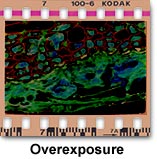 Overexposure - Color negative film that has a very dark image area is probably overexposed. Overexposure dramatically affects portions of the film containing highlights, which suffer from a significant or total loss of image detail. This error occurs because the film receives too much light, and is usually caused by shutter speeds that are too slow or excess illumination intensity. Tungsten-halogen lamps (12 volt and 50- or 100-watt) should be adjusted to a setting between 8.5 and 9.0 volts for optimum photomicrography color temperature and illumination. If the entire roll is overexposed, the fault is probably in the exposure settings on the camera system. Observe the camera ISO indicator to see if it matches the film speed, and check to see if the shutter speed is correctly set. Automatic camera systems can overexpose film if their lowest setting has a shutter speed too long for the amount of illumination. Reduce illumination intensity with neutral density filters, and perform test brackets to dial in exposure settings when using new specimens or films.
Exposure characteristics with color negative films are often difficult to judge. As mentioned above, these films exhibit a far greater exposure latitude than that found with transparency films, but examination of the results usually occurs at the film negative stage. Negative films will tolerate overexposure to a far greater degree than underexposure. Light areas on the negative translate into dark areas on the final print, and it is these regions that should be used to judge overall quality of the photomicrograph. If the film is overexposed, little detail will be present in light areas on the negative, and these areas, which translate into dark areas on the print, will likewise be devoid of detail when printed. When correctly exposed, negative films will reveal details in both light and dark regions of the negative, which translate into prints with good specimen rendition in highlights, background, and shadowed areas.
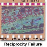 Reciprocity Failure - In optical microscopy, especially when light altering filters, polarizers, and prisms are added to the optical pathway as in many of the contrast enhancement modes (phase contrast, differential interference contrast, Hoffman modulation contrast, etc.), the proper film exposure is often longer than 1/2 second. Under these conditions, the film's reciprocity relationship (exposure equals light intensity multiplied by the exposure time) no longer holds, and the film requires additional exposure time to yield proper exposure.
This phenomenon is called reciprocity failure, and it occurs in all color and black & white photographic emulsions regardless of film speed, dye composition, or silver halide concentration. The term "failure" only indicates that the linear relationship between exposure time and light intensity no longer holds and does not indicate a failure of the film emulsion in terms of performance. Reciprocity failure can often be compensated simply by an increase in exposure times or processing conditions for black & white films, but this is not always the case with color negative and transparency films. Most color films have three color-sensitive dye layers, each of which has a slightly different characteristic curve position and slope, resulting in varied responses to the reciprocity effect with the potential to cause undesirable color shifts or casts. Often, both exposure times and color balance filters must be adjusted to compensate for very long or short exposures when using color films.
At very fast shutter speeds (1/500 second and faster), color negative films often experience color shifts and a lowering of contrast or reduced density in the negative, yielding prints that show substantial contrast loss. Color shifts are also common with reciprocity failure in color negative films, but these are usually easily remedied during printing, provided there is sufficient contrast to produce a suitable print. The only correction for reciprocity failure at fast shutter speeds is to increase the development time. When exposures are very long, typically under low-light conditions, exposure times must be dramatically extended, sometimes to the point of significant film speed loss. In fact, exposure times exceeding five minutes are not uncommon. When using color negative films, calculated exposure values can lead to negatives lacking shadow detail, but compensation by lengthy exposure often yields too much density in highlight areas, resulting in an increase in overall contrast. This is due to the fact that the reciprocity failure effect is greater in regions where specimen illumination is very low, a problem that can be overcome by increasing the amount of time the film is developed.
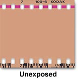 Unexposed Film - When the film displays only the orange mask associated with color negative film bases and does not have an apparent image produced on the emulsion, there is a possibility that it has not been exposed. This can be indicative of a serious problem with the film advance mechanism on automatic cameras or a malfunction of the camera shutter system. If the entire roll is unexposed, yet the camera appeared to be functioning properly during photomicrography, check to make certain the camera is receiving light from the microscope. Also examine the take-up spool to make sure it is working properly and the film is correctly attached. Many automatic exposure systems will not allow film to be exposed when insufficient light is being received, but older manual systems do not have this safety feature. In film rolls where only a single or couple of frames are unexposed, check the camera to make sure film is advancing properly.
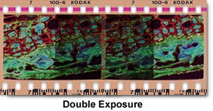
Double Exposure - Overlapping images are an indication of a double exposure where one section of film emulsion has been exposed twice. This is usually caused by a jammed camera shutter or improper advancement of the film. If the entire roll is double exposed, then it was probably run through the camera twice. Check the camera shutter to ensure it is working properly and inspect film advancement on automatic cameras. Film loaded into plastic or metal cassettes from bulk rolls can often cause incomplete frame advancement with automatic camera winding motors, especially when the film is rolled too tightly and causes the advance mechanism to bind. Check the film action on in-house loaded cassettes to make certain the film exits the cassette slit properly without sticking.
 Color Balance Errors - When the microscope illumination is not properly balanced for a particular film emulsion, shifts in color emerge as problems in resulting photomicrographs. Adjustment of color temperature for various photomicrography scenarios is discussed in great detail in the photomicrography section of the Olympus Microscopy Resource Center Microscopy Primer. Using film balanced for a daylight source (5500 K) in a microscope equipped for tungsten-balanced illumination will result in images that have an overall yellow cast in final prints. When examining negatives directly on a light table, scan for excessive shades of blue and cyan, which is an indication of exposure at too high of a color temperature. This is due to a dramatic mismatch in color temperature between the film and the light source, which is easily corrected with the proper use of color conversion and balance filters. With color negative films, color balance errors can often be corrected during printing, but the process operator must be informed about the proper color balance parameters for this type of film. The best method of obtaining satisfactory color prints is to supply the photo processor with several examples of color prints that have correct color tones.
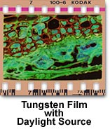 The problem of accidentally using tungsten-balanced film with a daylight-balanced light source is less common in photography through the microscope. Such a error can occur when using xenon and mercury arc lamps or photo flash tubes, which produce light with a color temperature around 5500 K. As discussed above, color temperature problems can be solved with the use of conversion filters that are commercially available. Microscopes that serve a dual purpose of reflected fluorescence (xenon or mercury illumination) and transmitted tungsten illumination are prone to this problem. Make certain the correct lamp and appropriate filters are being used when selecting film for photomicrography on a microscope configured with a daylight source of illumination.
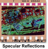 Specular Reflections - Bright spots on photomicrographs may arise from specular reflections from overhead lighting or auxiliary illumination from external light sources. These errors are particularly prevalent when making very long exposures in fluorescence photomicrography. To remedy this problem, either turn off overhead lights (or auxiliary illumination) or cover the area directly affected. On older microscopes a similar problem can occur when a beamsplitter is used between the viewing binocular head and the phototube. Circumvent the problem by adjusting the beamsplitter to a position where all microscope illumination is directed into the phototube. Reflections can also become a problem when specimens are imaged while bathed in solution or through a very thick cover glass and/or specimen holder (exceeding 1 millimeter) using long working distance objectives. There is no easy cure when imaging through thick glass, but reflections from the surface of aqueous solvent can be alleviated by using water immersion objectives.
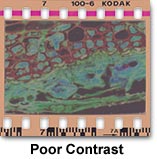 Poor Contrast - This is usually an indication that the substage condenser aperture diaphragm is opened too wide. To correct this problem, remove one of the eyepieces and insert a phase telescope into the eye tube or a Bertrand lens (if present) into the light path. While observing the rear focal plane of the objective, adjust the diaphragm iris opening until its diameter lies between 65 and 80 percent of the objective rear aperture. When using a reflected light microscope, adjust both the field diaphragm and the aperture diaphragm to improve contrast.
Using a high numerical aperture objective with a coverslip that has an incorrect thickness can also result in a loss of contrast and lack of image sharpness due to spherical aberration. Check the objective barrel to see if it matches the cover glass thickness. Coverslip contrast errors are caused by under or overcorrection for spherical aberration when microscope coverslips are either too thick or too thin. In this case, it will be impossible to accurately focus the microscope and obtain a sharp image. The solution to coverslip thickness problems is to replace an unsuitable coverslip with one of the correct thickness (usually a No. 1½ cover glass, which averages 0.17 millimeters thick with an acceptable range of 0.16 to 0.19 millimeters) or to use an objective equipped with a correction collar that can be adjusted to match coverslip thickness. If the coverslip thickness cannot be adjusted (i.e., it is glued onto the specimen slide) or if the thickness is unknown and an objective with a correction collar is not available, then the problem can sometimes be remedied by using an oil immersion objective of comparable magnification. Because the refractive index of immersion oil is very similar to that of the coverslip, thickness variations become less important. Reflected light objectives are corrected for observation and photomicrography without the use of a coverslip, so avoid coverslips with objectives of this type.
Focus and contrast can also be a problem when the specimen preparation is too thick or when the microscope slide is inadvertently examined upside down. Thickness errors can often be overcome by using long working distance objectives, but the best solution is to remake the specimen using thinner sections or to squeeze the coverslip more tightly over the preparation. The simple fix for an upside down microscope slide is to flip it over so the cover glass is facing the objective. Occasionally, several coverslips will stick together during specimen preparation and the resulting microscope slide will have two or more coverslips, causing spherical aberration problems in resulting photomicrographs. If this error is suspected, carefully examine the microscope slide containing the coverslips for the presence of interference fringes, which will occur because of the residual space between the two coverslips. Force the uppermost coverslip off using a pair of tweezers.
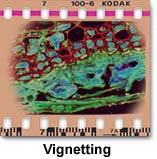 Vignetting - Photomicrographs may display a gradual darkening at the edge of the image area, which encompasses a circular pattern surrounding the image. If this occurs, check the substage condenser height and alignment and ensure the microscope is configured for proper Köhler illumination. If the condenser is adjusted too low in its rack, closing the aperture diaphragm to improve contrast may also cause darkening at the edge of the field. Also check the lamp filament to make certain it is centered and monitor the camera shutter speed so that it is not too fast to allow the film to respond (don't use shutter speeds faster than 0.01 second).
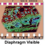 Field Diaphragm Visible - When photomicrographs have sharply focused, dark corners with straight edges, the problem is probably interference by the field diaphragm. Check to see if the field diaphragm is opened sufficiently to remain out of the viewfield, yet closed to the point of reducing glare. If adjustment of the field diaphragm does not cure the problem, check the projection lens magnification to ensure it completely fills the diagonal of the film frame. Microscope manufacturers usually offer a range of projection lenses in differing magnifications from 0.5x to 7.5x, with incremental sizes in between.
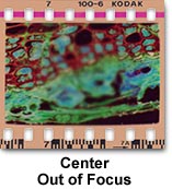 Center Focus Lost - When the edges of the photomicrograph are in sharp focus, but the center has lost its focus, the problem is probably curvature of field aberrations in the objective. Check the objective barrel to ensure it is marked plan, indicating the objective has been corrected optically for flatness of field. Uncorrected objectives will not produce a sharp image across the entire microscope viewfield. This error also occurs in reflected light specimens when the specimen is slightly tilted or mounted at an angle. To correct the problem, remount the specimen or use modeling clay and a compressor to provide an adjustable level base.
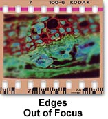 Edges Out of Focus - This error also will occur when using objectives lacking plan (flat field) correction. Most objectives display a finite amount of field curvature aberration due to distance variations in the path of on-axis and off-axis image forming light waves. In this case, use the fine focus knob to drift through focus from the edges to the center, in order to confirm field curvature aberrations. Replace uncorrected objectives with plan objectives to solve the aberration problem. If objective replacement is impossible, limit the area recorded in the photomicrograph to the center of field whenever possible, or install a projection lens of higher magnification to reduce the field size.
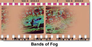
Bands of Fog - When photomicrographs show banded areas that are fogged or washed out, then the problem is probably caused by opening the camera back very briefly in the light. This condition can also occur when the camera back has a light leak along the hinges or catch. The degree of fogging will depend upon the length of time the back was open and the brightness of room light. To alleviate this problem, make certain the film is completely rewound before opening the camera back. If a light leak is suspected, have a qualified service technician inspect the camera back.
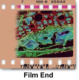 Film End - If part of a frame is missing, damaged or fogged, then it probably was at the end of the film roll. This error often occurs when trying to squeeze that extra frame from a roll of film. During processing in the film laboratory, the end frame is often very close to the area where processors place clips to hold several rolls together. There is no method to prevent this problem, but it can be minimized by restricting critical photomicrography images to the number of frames indicated on the film magazine.
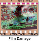 Damaged Film - Curls, buckles or scratches in the film are an indication of mishandling of the film during loading or unloading the camera back, or during mounting of the transparencies. This error is often seen in 35 millimeter cassettes that have been loaded from bulk film rolls. Prevention includes being very careful with film during handling and alerting the film processing laboratory about the problem. If the problem persists, contact a new processing laboratory.