In the mid-1950s, a French optics theoretician named Georges Nomarski modified the Wollaston prism used for detecting optical gradients in specimens and converting them into intensity differences. Today there are several implementations of this design, which are collectively called differential interference contrast (DIC). Living or stained specimens, which often yield poor images when viewed in brightfield illumination, are made clearly visible by optical rather than chemical means.
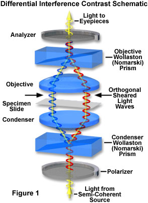
In transmitted light DIC, light from the lamp is passed through a polarizer located beneath the substage condenser, in a manner similar to polarized light microscopy. Next in the light path (but still beneath the condenser) is a modified Wollaston prism that splits the entering beam of polarized light into two beams traveling in slightly different directions. The Wollaston prism is composed of two quartz wedges cemented together, from which emerging light rays vibrate at 90 degrees relative to each other with a slight path difference. A different Wollaston prism is needed for each objective of different magnification. Wollaston prisms are usually loaded into a revolving turret on the condenser, which allows the microscopist to rotate the appropriate prism into the light path when changing magnifications.
Wollaston Prism Wavefronts
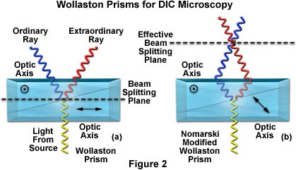
Examine how a Wollaston prism acts to split or shear a polarzied beam of light into an ordinary and an extraordinary ray oriented in mutually perpendicular directions.
Start Tutorial »The plane-polarized light, vibrating only in one direction (East-West) perpendicular to the propagation direction of the light beam, enters the beam-splitting modified Wollaston prism and is split into two rays, vibrating perpendicular to each other. These two rays travel close together but in slightly different directions (see Figure 2). The rays intersect at the front focal plane of the condenser, where they pass traveling parallel and extremely close together with a slight path difference, but they are vibrating perpendicular to each other and are therefore unable to cause interference. The distance between the rays, called the shear, is so minute that it is less than the resolving ability of the objective.
The split beams enter and pass through the specimen where their wave paths are altered in accordance with the specimen's varying thickness, slopes, and refractive indices. These variations cause alterations in the wave path of both beams passing through areas of any specimen details lying close together. When the parallel beams enter the objective, they are focused above the rear focal plane where they enter a second modified Wollaston prism that combines the two beams at a defined distance outside of the prism itself. This removes the shear and the original path difference between the beam pairs. As a result of having traversed the specimen, the paths of the parallel beams are not of the same length (optical path difference) for differing areas of the specimen.
In order for the beams to interfere, the vibrations of the beams of different path length must be brought into the same plane and axis. This is accomplished by placing a second polarizer (analyzer) above the upper Wollaston beam-combining prism. The light then proceeds toward the eyepiece where it can be observed as differences in intensity and color. The design results in one side of a detail appearing bright (or possibly in color) while the other side appears darker (or another color). This shadow effect bestows a pseudo three-dimensional appearance to the specimen.
In some microscopes, the upper modified Wollaston prism is combined in a single fitting with the analyzer incorporated above it. The upper prism may also be arranged so it can be moved horizontally. This allows for varying optical path differences by moving the prism, providing the user a mechanism to alter the brightness and color of the background and specimen. Because of the prism design and placements, the background will be homogeneous for whatever color has been selected.
Differential Interference Contrast
Explore how changing the bias in the upper Wollaston prism affects image contrast in the DIC microscope.
The color and/or light intensity effects shown in the image are related especially to the rate of change in refractive index, specimen thickness, or both. Orientation of the specimen can have pronounced effect on the relief-like appearance and often, rotation of the specimen by 180 degrees changes a hill into a valley or visa versa. The three-dimensional appearance is not a representation of the true geometric nature of the specimen, but is an exaggeration based on optical thickness. It is not suitable for accurate measurement of actual heights and depths.
There are numerous advantages in DIC microscopy as compared to phase contrast microscopy. With DIC, it is possible to make fuller use of the numerical aperture of the system and to provide optical staining (color). DIC also allows the microscope to achieve excellent resolution. Use of full objective aperture enables the microscopist to focus on a thin plane section of a thick specimen without confusing images from above or below the plane. Annoying halos, often encountered in phase contrast, are absent in DIC images, and suitable achromat and fluorite objectives can be used for this work.
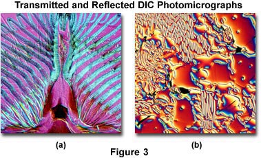
A downside is that plastic tissue culture vessels and other birefringent specimens yield confusing images in DIC, hence Hoffman modulation contrast is recommended for tissue culture work. Also, high-quality apochromatic objectives are now designed to be suitable for DIC. Figure 3 presents transmitted and reflected light DIC photomicrographs of the mouthparts of a blowfly (transmitted DIC; Figure 3(a)) and surface defects in a ferro-silicate alloy (reflected DIC; Figure 3(b)). Both photomicrographs were made using a retardation plate with a 10x objective.
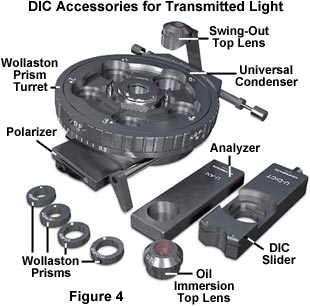
The equipment needed for DIC microscopy includes a polarizer, a beam-splitting modified Wollaston prism below the condenser, a beam-recombining modified Wollaston prism above the objective, and an analyzer above this upper prism. Individual prisms are required (for each objective) below the condenser (Figure 4). For the upper prism, a single prism may serve for all objectives. The upper prism can be moved laterally.
The distance of the placement of the lower prism in relation to the front focal plane of the condenser and the distance of the upper prism from the back focal plane of the objective are quite critical. Manufacturers therefore designate which of their objectives are suitable for their particular DIC apparatus.
The DIC condenser contains four or more prisms, a brightfield opening with aperture diaphragm for regular brightfield work, and/or several light annuli. The light annuli, together with phase objectives, enable the microscopist to make quick comparisons between phase contrast and DIC images. A rotatable polarizer is fitted below the prisms. Use of full objective aperture enables focusing on a thin plane section of a thick specimen without confusing images from above or below the plane that is being focused on; this is called Optical Sectioning. Larger apertures also yield better resolution in optical microscopy.
The color and/or light intensity effects shown in the image are related especially to the rate of change in refractive index, thickness or both in details or adjacent areas of the specimen. The image appears 3-dimensional. This appearance does not represent the true geometric nature of the specimen, but is an exaggeration based on optical thickness, and is not suitable for accurate measurement of actual heights and depths. Optical thickness refers to changes in the light path resulting from change in refractive index or actual thickness or some combination of both of these variables.
As mentioned above, at the gray setting of the movable upper prism, the 3-dimensionality is most marked. Orientation of the specimen can significantly improve the relief-like appearance. Sometimes the rotation of the specimen 180 degrees changes a hill into a valley or vice versa; hence the interpretation of the image must be done with caution. The darker appearance on one side and the lighter appearance on the other side of a detail greatly improve the visibility by giving a pseudo-relief effect.
To configure a microscope for DIC contrast enhancement, the following steps should be considered:
- Place the DIC condenser into the substage condenser holder of the microscope and fit the DIC Wollaston prism into a slotted nosepiece or in slots behind each objective. Using a 10X objective and the condenser at the brightfield (0) position and polarizer in the light path, set up Köhler illumination with a specimen in place on the stage. Move the specimen out of the light path and remove one of the eyepieces.
- Insert a phase focusing telescope into the eyepiece tube and, while looking at the back focal plane of the objective, rotate the screw of the upper prism until you see a diagonal blackish line appearing at the center of the back of the objective. Now slightly rotate the substage polarizer to make the black line appear as black as possible. This, in effect, is adjusting the polarizer so that it is crossed (at a 90 degree angle) with the analyzer that is situated above the upper prism. Make sure the condenser aperture diaphragm is open to 2/3 to 4/5 of the back lens diameter of the objective.
- Remove the focusing telescope and return the regular eyepiece to the eyetube. Rotate the condenser turret to bring the appropriate lower prism into the light path; this is usually marked by the red or white 10 setting on the turret. Move the specimen back into the light path. Now you may use the knob of the upper prism to translate it back and forth laterally to achieve the desired effect or color. You may also rotate the stage to change the orientation of the specimen to improve the effect.
- Similar steps are taken for each objective being used, making sure the microscope is properly configured for Köhler illumination for each objective in turn by adjusting both the field and aperture diaphragms.
These are numerous advantages in DIC microscopy as compared particularly to phase microscopy:
- It is possible to make fuller use of the numerical aperture of the system because, unlike phase contrast microscopy, there is no substage annulus to restrict the aperture; Köhler illumination is properly utilized.
- There are no confusing halos as may be encountered in phase images.
- Images can be seen in striking color (optical staining) and in 3-dimensional shadowed-like appearance. The visibility of outlines and details is greatly improved, and the photomicrography of these images is striking in color and detail.
- Regular planachromats or achromats (also suitable for ordinary brightfield work) can be used if the manufacturer states that such objectives are designed for their apparatus.
There are several disadvantages or limitations in DIC:
- The equipment for DIC is quite expensive because of the many prisms that are required.
- Birefringent specimens such as those found in many kinds of crystals may not be suitable because of their effect upon polarized light. Similarly, specimen carriers, such as culture vessels, Petri dishes, etc., made of plastic may not be suitable. For such specimens, Hoffman modulation contrast may be a better choice.
- For very thin or scattered specimens, better images may be achieved using phase contrast methods.
- Apochromatic objectives may not be suitable because such objectives themselves may significantly affect polarized light.
Once again, like so many of the contrasting enhancing techniques, we find that manipulation of light at the front focal plane of the condenser and at the rear focal plane of the objective has significant effect upon the appearance of the image that is visualized through the eyepiece.