The quarter wavelength retardation plate is a common optical accessory for polarized light microscopy that operates by introducing a relative phase shift of 90 degrees between the orthogonal wavefronts (ordinary and extraordinary) passing through when the plate is illuminated with linearly polarized light. A phase shift of 90 degrees between the ordinary and extraordinary components converts the incident linear polarized light vibrations into either elliptical or circularly polarized light. Quarter wavelength retardation plates are useful for the qualitative analysis of conoscopic and orthoscopic images, and for the assessment of optical path differences in birefringent specimens.
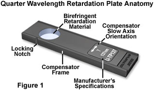
The simple anatomy of a quarter wavelength retardation plate is presented in Figure 1 for a typical commercial unit. Retardation materials employed in construction of the plate vary according to the application, but usually consist of either an optical mineral thin section (such as quartz or mica) or a highly aligned birefringent linear organic polymer sandwiched between two isotropic optically flat glass plates. Regardless of the material used in producing retardation, the optical path difference (usually inscribed on the retardation plate frame) and optical axis orientation of the birefringent retarding material must be carefully controlled so that the plate can add a known retardation value to both the high and low refractive index azimuths of orthogonal wavefronts. As illustrated in Figure 1, the birefringent retardation material is positioned in the window of a rectangular frame that is inserted into the microscope optical pathway at a 45-degree angle with respect to the transmission orientations of the polarizer and analyzer. The direction of the slow (high refractive index) axis of the wavefront ellipsoid is indicated on the retardation plate frame as a double-headed arrow accompanied by the Greek symbol for "gamma" (γ). In most cases, the slow axis orientation is perpendicular to the long dimension of the retardation plate frame, although this fact should be verified before attempting to use the instrument. Modern quarter wavelength retardation plates are built in a frame having standardized DIN dimensions (6 × 20 millimeters) that will enable their use in a variety of microscopes.
The quarter wavelength retardation plate is designed to introduce a relative retardation of exactly one-quarter wavelength (in the green or 550 nanometer region), or 90 degrees, between the ordinary and extraordinary wavefronts passing through the plate when the birefringent retardation material is illuminated by linearly polarized light at a 45-degree incident angle to the index ellipsoid, as illustrated in Figure 2. The resulting phase shift converts the linear input wavefront to a circularly polarized output wavefront. This action occurs because the orthogonal ordinary and extraordinary components have equal amplitudes when linear light oriented at a 45-degree angle to the principal (the fast or slow) axes is incident on a quarter wavelength retardation plate. In a similar manner, the quarter wavelength plate will convert an incoming circularly polarized wavefront into a linearly polarized wavefront.

Commercial quarter wavelength retardation plates are specified by their linear retardation, which is 137 nanometers for the device illustrated in Figure 1 that is designed to operate in light having a principal wavelength of 548 nanometers (in the green region). In polarized light microscopy applications, the quarter wavelength plate is utilized in a similar manner to the full wave retardation plate in order to determine whether the combination of a weakly birefringent specimen and the plate (oriented at a 45-degree angle to the polarizer and analyzer) yield higher or lower order interference colors. However, the quarter wavelength plate has been largely supplanted by the full wave retardation plate due to the superior sensitivity of the latter in producing color changes that can be readily observed. In cases where birefringent specimens display higher order interference colors between crossed polarizers without a retardation plate, then the quarter wavelength plate can often be used to advantage over the full wave plate to determine optical path differences.
This concept is illustrated in Figures 3(a) and 3(b) for a polished thin section of tactic skarn, which contains inclusions that exhibit first and second order interference colors in polarized light without the presence of a retardation plate or compensator. When a first order retardation plate is employed to determine the optical sign of this birefringent ore, the interference colors are shifted up the Michel-Levy chart by a single wavelength and can lead to confusion during quantitative analysis. Conversely, using a quarter wavelength plate instead produces the customary first order yellow for the fast optical axis (Figure 3(a)) and second order blue hue for the slow axis (Figure 3(b)), allowing for easier identification of the optical properties.
The primary use for quarter wavelength retardation plates is to determine the optical sign of birefringence from interference figures observed in conoscopic mode with a Bertrand lens (Figures 3(c) and 3(d)). Insertion of a quarter wavelength retardation plate resolves the center of a uniaxial interference figure (Figure 3(c)) into two dark spots (Figure 3(d)). If the dark spots are positioned at right angles to the slow vibration axis of the compensator crystal (in quadrants two and four; Figure 3(d)), then the sign of birefringence for the crystal is positive. Conversely, if the dark spots are positioned parallel to the compensator crystal slow axis (in quadrants one and three; Figure 3(d)), the crystal has a negative sign of birefringence. Note that other rings in the interference pattern are translated either towards the center or the periphery of the pattern according to the optical sign. The interference pattern in Figure 3(c) was generated conoscopically using a polished thin section of the mineral lamproite, which exhibits negative birefringence. A similar technique can be employed to determine the optical sign of birefringence for biaxial crystals.
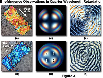
The extinction bands in polarized light images can be eliminated for image analysis purposes by inserting crossed quarter wavelength retardation plates into the microscope optical path with the specimen sandwiched between the two plates. In effect, the retardation introduced by the first quarter wavelength plate is precisely cancelled by the second, so that light reaching the analyzer contains only the retardation introduced by the specimen itself. In practice, one of the retardation plates is inserted into the nosepiece or intermediate tube slot with the slow vibration axis oriented Northeast-Southwest (by convention in modern microscopes). The second plate must be placed between the polarizer and the specimen (usually in or very near the condenser) with the slow axis oriented Northwest-Southeast. The two plates should be fabricated from the same material in order to completely eliminate extinction bands. If the two plates are accurately aligned, a minimum change of polarization colors will be observed in birefringent specimens as they are rotated through 360 degrees with the microscope circular stage. Images of purified riboflavin (Vitamin B2) crystallites in polarized light (Figure 3(e)) alone, and with quarter wavelength retardation plates inserted beneath the stage and above the objective rear aperture are illustrated in Figures 3(e) and 3(f), respectively. Note that the extinction regions of the spherulitic crystallite present in Figure 3(e) have been eliminated by the application of two quarter wavelength plates (Figure 3(f)), which more clearly defines the texture.
In summary, the quarter wavelength retardation plate is capable of detecting optical path differences of (plus or minus) one-half wavelength by rotating the stage through 90 degrees. In this regard, the plate has a sensitivity range lying between the Bräce-Köhler and quartz wedge compensators and overlaps with the de Sénarmont compensator. Unlike many of the adjustable compensators, the quarter wavelength retardation plate can be effectively used in white light, but the most accurate results are obtained when the plate is coupled to the wavelength for which the crystal was prepared (for example, 548 nanometer green light for a 137 nanometer plate). The retardation plate can also be used to produce circularly polarized light by inserting it into the optical path above the polarizer.


