Conventional widefield and laser scanning confocal fluorescence microscopy are widely employed techniques that rely on illumination of fluorophore-labeled specimens with a broad cone of light. The limited spatial resolution demonstrated by widefield fluorescence microscopy, especially along the optical axis, often renders it difficult to differentiate between individual specimen details that are overpowered by background fluorescence from outside the focal plane.
Confocal microscopes employ a pair of pinhole apertures strategically placed in conjugate planes near the illumination source and detector to produce thin optical sections devoid of background fluorescence. Multiphoton excitation microscopy goes a step further by restricting the illuminated specimen area to an ellipsoid having micron or sub-micron dimensions. Both confocal and multiphoton fluorescence microscopy produce optical sections of similar size. However, multiphoton excitation reduces the amount of secondary fluorescence produced by fluorophores through use of near-infrared long wavelength illumination and restriction of excitation events by the laser source to the objective focal volume.
In contrast, total internal reflection fluorescence microscopy (TIRFM) employs the unique properties of an induced evanescent wave to selectively illuminate and excite fluorophores in a restricted specimen region immediately adjacent to a glass-water (or glass-buffer) interface. The basic concept of TIRFM is simple, requiring only an excitation light beam traveling at a high incident angle through the solid glass coverslip or plastic tissue culture container, where the cells adhere. Refractive index differences between the glass and water phases regulate how light is refracted or reflected at the interface as a function of incident angle. At a specific critical angle, the beam of light is totally reflected from the glass/water interface, rather than passing through and refracting in accordance with Snell's Law. The reflection generates a very thin electromagnetic field (usually less than 200 nanometers) in the aqueous medium, which has an identical frequency to that of the incident light. This field, called the evanescent wave or field, undergoes exponential intensity decay with increasing distance from the surface.
The characteristic distance for decay of the evanescent wave intensity is a function of the incident illumination angle, wavelength, and refractive index differences between media on each side of the interface. Fluorophores residing near the glass-liquid surface can be excited by the evanescent field, provided they have electronic transitions that occur in or very near the wavelength bandwidth of the illuminating light beam. Because of the exponential falloff of evanescent field intensity, fluorophores farther away from the surface avoid being excited, which leads to a dramatic reduction of unwanted secondary fluorescence emission from molecules that are not in the primary focal plane. The effect enables production of high-contrast images of surface events with a significant increase in signal-to-background ratio over classical widefield techniques.
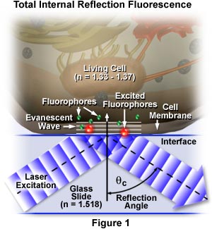
The concept of TIRFM is schematically presented in Figure 1, which depicts selective excitation of fluorophores in an tissue culture cell (refractive index, n = 1.33 to 1.37) resting on the surface of a glass slide (refractive index, n = 1.518). Wavefronts from a blue laser excitation source pass through the glass and are reflected from the glass-buffer boundary at a critical angle, θ(c), establishing an evanescent wave that travels several hundred nanometers into the cell membrane. Fluorophores in the membrane near the glass interface (small green spheres) are excited by the evanescent wave and subsequently emit secondary fluorescence (red), while those farther away from the interface are not excited.
Excitation by an Evanescent Wave
Explore TIRFM excitation of fluorophores residing in the membrane of a living cell in tissue culture with a virtual tunable laser.
Start Tutorial »Total internal reflection fluorescence is employed to investigate the interaction of molecules with surfaces, an area that is of fundamental importance to a wide spectrum of disciplines in cell and molecular biology. Examples are binding and triggering of cells by hormones, neurotransmitters, and antigens; cell adhesion to surfaces; electron transport in the mitochondrial membrane; cytoskeletal and membrane dynamics; cellular secretion events; polymer translation near an interface; single molecule interactions; and surface effects on reaction rates. In a majority of these studies, functionally relevant fluorophores bound to the surface and those in the surrounding medium exist in an equilibrium state. When these molecules are excited and detected with a conventional widefield fluorescence microscope, the resulting fluorescence from those fluorophores bound to the surface is often swamped by the overwhelming fluorescence from a much larger population of non-bound molecules inhabiting the adjacent detection volume. Constraint of the optical field to a refractive index interface is the basis for all total internal reflection spectroscopy, spectrometry, and microscopy investigations.
Living cells in culture provide an excellent candidate for TIRFM investigations. The technique enables selective visualization of contact regions between individual cells and the substrate, even in specimens where fluorescence from areas outside the surface would obscure important fluorescent information concerning adhesion points. Because illumination is restricted to the interface regions and does not penetrate the specimen bulk, living cells tend to survive longer under fluorescence observation using TIRFM techniques. This feature enables microscopists to increase the length of observations, and to perform time-lapse cinemicrography for extended periods, often ranging for many hours or even one or more days.
TIRFM can also be utilized on featureless non-microscopic specimens to measure fluorophore concentrations as a function of distance from the interface, or to record binding/unbinding equilibria and kinetic rates at a biological surface. Other applications include single molecule fluorescence experiments and model membranes, which have been constructed using the substrate for mechanical support. The technique is also useful for investigating the emission of fluorophores bound to surfaces as a function of molecular dipole orientation. These and other experiments are designed to examine the chemistry and physics of interfaces themselves, and should continue to be the focus of TIRFM studies in many diverse fields.
Theory of Total Internal Reflection
The behavior of a collimated light beam upon refraction or reflection from a plane surface is fundamental to the understanding of TIRFM. Light passing between two media of varying refractive index is either refracted as it enters the second medium or it is reflected at the interface, depending upon the incident angle and the difference in refractive index between the two media. In situations where the light beam is propagating through a medium having a high refractive index and encounters a boundary to a medium of lower refractive index, it is refracted according to Snell's Law:
where n(1) is the higher refractive index medium and n(2) is the medium of lower refractive index. The incident wave is positioned at angle θ(1) from the normal, while θ(2) represents the angle of light refracted at the interface into the medium of lesser refractive index. As the incident angle slowly increases (relative to the normal), it reaches a point termed the critical angle where the refraction angle is 90 degrees. At higher incident angles, light is completely reflected at the interface (total internal reflection), and no significant amount is refracted into the bulk phase of the medium having a lower refractive index. In biological investigations involving living tissue culture cells or similar studies of cytoplasmic components, n(1) represents the refractive index of the glass microscope slide or coverslip (n = 1.518), while n(2) is the refractive index of the aqueous buffer solution or internal cellular components (n = 1.33 to 1.37). Therefore, n(1) is greater than n(2), and when θ(1) exceeds the critical angle θ(c), total internal reflection occurs within the glass adjacent to the liquid medium. The critical angle is defined by the equation:
or
sinθ(c) = n(2)/n(1)which is more commonly expressed as:
θ(c) = sin-1n(2)/n(1) = sin-1n(2,1)For angles less than θ(c), a majority of the incident light propagates directly through the interface with a refraction angle measured from the normal as defined by Snell's Law (discussed above). Even in this situation, some of the incident light is reflected back into the glass. However, for all angles greater than the critical angle, total internal reflection is achieved and a vast majority of the light is reflected. A small portion of the reflected light penetrates through the interface, and propagates parallel to the surface in the plane of incidence creating an electromagnetic field in the liquid adjacent to the interface. This field, as described above, is termed the evanescent field and is capable of exciting fluorophores residing in the immediate region near the interface.
The transition from refraction to total internal reflection occurs without any discontinuities, rather than being a sudden new phenomenon appearing at the critical angle. As the incident angle becomes larger, the transmitted (refracted) beam becomes weaker while the reflected beam slowly acquires more intensity. At small incident angles, light waves passing through to the liquid are sinusoidal, with a characteristic period. As the incident angle approaches the critical value, the period becomes longer and refracted rays propagate increasingly parallel to the surface of the interface. When the critical angle is achieved, the period becomes infinite and the refracted light produces wavefronts that are perpendicular (normal) to the surface.
Evanescent Field Penetration Depth
Discover how the evanescent field penetration depth is altered as a function of refractive index differences between the two phases surrounding the interface, the critical angle of incident illumination, and the laser excitation wavelength.
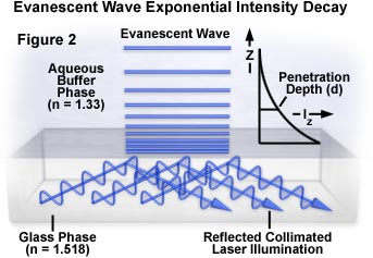
For a light beam having a finite width, the evanescent wave created at the interface can be described as partially emerging from the solid into the liquid medium and traveling for some distance before re-entering the solid phase. This propagation distance, called the Goos-Hänchen shift, can be measured when the beam width is restricted to one or several wavelengths. The size of this shift ranges from a fraction of a wavelength when the incident light is perpendicular to the interface, to infinite at the critical angle, which corresponds to the refracted beam skipping along the surface. Wider beams (those having a width much larger than a few wavelengths) produce an evanescent field whose intensity can be measured in units of energy per unit area per second. The evanescent field intensity decays exponentially (Figure 2) with increasing distance from the interface according to the equation:
where I(z) represents the intensity at a perpendicular distance z from the interface and I(o) is the intensity at the interface. The characteristic penetration depth (d) at λ(o), the wavelength of incident light in a vacuum, is given by:
The penetration depth, which usually ranges between 30 and 300 nanometers, is independent of the incident light polarization direction, and decreases as the reflection angle grows larger. This value is also dependent upon the refractive indices of the media present at the interface and the illumination wavelength. In general, the value of d is on the order of the incident wavelength, or perhaps somewhat smaller. When the incident angle equals the critical value, d goes to infinity, and the wavefronts of refracted light are normal to the surface. Experimental measurements of fluorescent intensity as a function of distance from the interface in a typical TIRF investigation are listed in Table 1 for a set of identical fluorophores.
Fluorescence Intensity versus Penetration Depth
| Distance (Nanometers) | Relative Intensity |
|---|---|
| 1 | 0.99 |
| 10 | 0.92 |
| 100 | 0.43 |
| 1000 | 0.0002 |
Table 1
Evanescent wave intensity at the surface (I(o)) is a function of both the incident angle and the polarization components of the light beam. The I(o) intensities observed for polarized vibration vectors can be discussed in terms of a coordinate system arranged to display all three orthogonal directions, as illustrated in Figure 3. The plane of incidence (the x-z plane) is defined as being parallel to the exciting light beam with the x-direction parallel and the z-direction perpendicular to the interface surface. The y-direction then becomes normal to the plane of incidence.
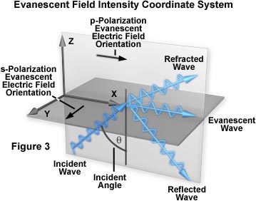
Two independent incident light polarization directions, termed p and s, are possible. These are electric field vectors parallel (p) and perpendicular (s) to the plane of incidence defined by the paths of the incident and reflected light beams. The evanescent electric field vector for the s-polarized incident light is perpendicular (or normal) to the plane of incidence. A non-zero longitudinal component and phase lag manifests the p-polarized incident light, which has an evanescent electric field vector direction that remains in the plane of incidence. The longitudinal component induces the p-polarized light electric field vector to "cartwheel" along the interface and produce elliptical polarization of the evanescent field in the plane of propagation. A spatial period of:
is observed for the p-polarized electric field vectors. The spatial period is not affected by the refractive index or dielectric properties of the resident medium (aqueous buffer or water). Instead, it is determined by the spacing of the incident light wavefronts in the glass medium as they intersect the interface. When the incident angle is reduced from the supercritical range to the critical angle and lower, the longitudinal component disappears and the electric field component in the x-direction simultaneously vanishes.
The evanescent field intensities at the interface (z = 0) for the incident p and s components are complex expressions given by the following series of equations:
where n represents the refractive index ratio (n(2)/n(1)), which is less than unity, and θ is the incident angle. For s-polarized incident light, the total evanescent intensity is equal to the y-component, I(y), while the evanescent intensity for p-polarized incident light is composed of both the x and z components (I(x) and I(z)). As discussed above, the y intensity is linearly polarized, but the x and z intensities are elliptically polarized due to the fact that the electric fields are 90-degrees out of phase with each other.
Evanescent Field Intensity Profiles
Examine how changes in the incident angle affect evanescent wave intensity and the relationships between the electric field vectors of parallel and perpendicular components of the incident beam.
Start Tutorial »The p and s evanescent intensities are illustrated in Figure 4 as a function of incident angle for transmitted light in the lower refractive index medium when passed through an interface composed of fused quartz (n(1) = 1.46) and water or an aqueous buffer solution (n(2) = 1.33). These calculations assume a condition of total internal reflection and require a critical angle of 65.7 degrees for the refractive indices listed. Intensity, plotted on the ordinate, is expressed as the ratio of evanescent intensity at the interface (z equals zero) to the incident intensity for each polarization angle. It is interesting to note that the evanescent intensities for both polarization orientations exhibit a range between one and five times that of the plane wavefront incident intensity for angles within 15 degrees of the critical angle.
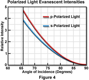
Although not illustrated in Figure 4, evanescent intensities of the polarized components can be extended (without breaks) to the subcritical angle region, which is good evidence for the continuity of the transition to total internal reflection. As the incident angle approaches 90 degrees, the evanescent intensities drop almost to zero.
Polarized Light Evanescent Intensities
Discover how evanescent field intensities vary as a function of critical angle and the refractive index of the glass medium.
In typical TIRFM experiments, a Gaussian laser beam is focused at a narrow angle of convergence to produce evanescent illumination that resembles an elliptical Gaussian profile, as depicted in Figure 5(a). Intensity profiles of a total internal reflection region (2 degrees greater than the critical angle) are presented in the figure, with illumination provided by a Gaussian profile beam emitted by a continuous wave argon-ion laser. The polarization and penetration depth are approximately equal to those exhibited by a single infinite plane wave.
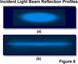
To produce the laser reflection profiles presented in Figure 5, a glass coverslip surface coated with a thin layer of the chromophore 3,3'-dioctadecylindocarbocyanine (Dil) is illuminated with the argon-ion laser and images were recorded in air through a 10x objective having a numerical aperture of 0.25 and achromatic correction. The beam is slightly defocused at the reflection surface in Figure 5(a), but has tight focus in Figure 5(b). The long thin stripe exhibited by the focused beam in Figure 5(b) is due a greater convergence angle than the beam in Figure 5(a), and a mean angle within a few degrees of the critical angle.
TIRFM with Intermediate Dielectric Layers
Often, the interface in actual TIRFM experiments is not so clearly defined as a simple boundary between the glass coverslip and an aqueous buffer solution. A good example is the case of a biological membrane or lipid bilayer interposed between the glass and buffer solution at the bottom surface of a tissue culture vessel. Another often-utilized example is a metallic thin film coating, which displays some interesting features. These interfaces are described as three-layer systems in which incident light travels from the glass medium (n(1) = 1.518) through the intermediate layer (having a refractive index referred to as n(i)) toward the lower refractive index aqueous buffer medium (n(2) = 1.33).
Among the interesting features of three layer systems is that insertion of the intermediate layer does not hinder total internal reflection, regardless of the layer's refractive index. Instead, the question is whether reflection occurs at the n(1):n(i) interface or the n(i):n(2) interface. Most intermediate layers will be exceedingly thin (10 to 30 nanometers) so the identity of the interface supporting total internal reflection is not important for qualitative studies.
The characteristic depth of the evanescent wave is still described by the relationships discussed above, regardless of the refractive index and thickness of the intermediate layer. However, the properties of the intermediate layer will affect the overall penetration distance of the evanescent field, as measured from the surface boundary of the aqueous medium. The evanescent intensity at the interface (z equals zero) is affected by the intermediate layer. Thin layers (around 20 nanometers) of metallic film produce dramatic effects in this regard. The s-polarized evanescent intensity becomes negligible, but the p-polarized intensity is actually enhanced for a very narrow band of incident angles and becomes an order of magnitude brighter just above the critical angle. This "resonance" effect is attributed to excitation of a surface plasmon mode at the metal/water interface. Plots of intensity (not illustrated) versus incident angle yield a peak, which is termed the surface plasmon angle. For an aluminum film residing between a glass/water interface, this angle is greater than the critical angle for total internal reflection. Such an illumination enhancement is remarkable when one considers that the thin metallic film is almost opaque.
Among the practical consequences of metallic film effects is that these films can be employed to quench fluorescence within 10 nanometers of the surface, but TIRFM can still selectively excite fluorophores in the 10- to 200-nanometer region above the interface. In addition, it has been noted that a light beam incident (through glass) on a 20-nanometer aluminum film does not require collimation to produce total internal reflection. Light rays incident at the surface plasmon angle will create a strong evanescent wave to excite fluorophores, while the rays having too low or high of an incident angle will produce a negligible field in the buffer layer. This phenomenon may be utilized to allow substitution of uncollimated incident illumination for many TIRFM experiments. In addition, the presence of a metallic film leads to a highly polarized evanescent wave, regardless of the purity of the incident polarization.
Another point to consider is that irregularities in the intermediate layer can induce scattering of the incident light beam, which then propagates in all directions through the medium of lower refractive index (the aqueous buffer layer). Light scattering does not appear to pose a significant experimental problem to specimens such as biological cells in culture. This is due to the fact that excitation of chromophores by scattered light is far less than excitation by the evanescent field, producing a correspondingly smaller contribution to secondary fluorescence emission intensity.
Fluorescence Emission at the Reflection Interface
Fluorophores existing in close proximity to an interface do not emit light isotropically, unlike those dispersed in bulk solution. Instead, secondary fluorescence emission is produced in a complex spatial pattern that is highly dependent upon the orientation of the fluorophore transition dipoles with respect to the interface geometry. Other factors that govern emission parameters are the dielectric properties of the media comprising the interface, which often impose different propagation speeds and directions on light emitted by fluorophores. Also, in many fluorescence microscopy experiments, fluorophores are bound to biological structures or other complex assemblies that impose strict orientational limitations or requirements, and often have association constants exceeding the fluorescence lifetime.
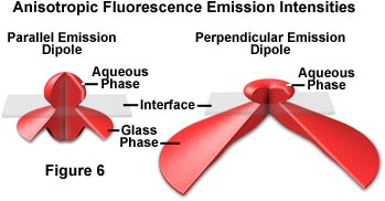
When fluorophores near an interface are modeled as constant power oscillators, the radiated emission intensity in all directions for molecules oriented perpendicular and parallel to the interface are presented in Figure 6. In each case, the transition dipole is positioned within the medium of lower refractive index (water or buffer) at a distance z' equal to 80 nanometers from the quartz surface. The fluorophores are assumed to be azimuthally unoriented with the dipole parallel to the surface in Figure 6(a) and perpendicular to the surface in Figure 6(b). In both cases, the fluorescence emission distribution patterns are complex and highly non-uniform.
In many TIRFM experiments, fluorescence emission is gathered by an objective that is positioned above the specimen on the water/buffer side of the interface. Under these circumstances, even low numerical aperture objectives are capable of capturing a majority of the emission to yield reasonable results from TIRFM experiments. The situation is somewhat different when the objective is placed beneath the glass layer and fluorescence emission is collected after it passes through the glass medium. Because fluorophores are oriented perpendicular to the surface in many cases, the emission patterns require higher numerical apertures for efficient collection of secondary fluorescence (see figure 6). Fluorescence emission polarization and lifetimes are also affected by the fluorophore's proximity to the interface. This results in a complex relationship between fluorescence intensity, distance from the interface, and fluorophore orientation, which renders accurate measurements of these parameters difficult.
Conclusions
An increasing number of important biochemical and cell biology investigations are now being conducted using TIRFM techniques developed over the past few years. The basic theory has been well established and practical implementation of the technique is now within the reach of many laboratories. Configuration of an upright or inverted microscope for TIRFM is relatively easy to accomplish using a laser light source, and several investigators have also demonstrated that these experiments can be conducted with traditional arc-lamp illumination sources, provided additional modifications are made. The technique is compatible with standard epi-fluorescence, brightfield, darkfield, phase contrast, and differential interference contrast illumination modes, and can be utilized to simultaneously record and compare images from several observation methods. This enables investigators to localize fluorescence emission to specific regions within cells, membranes, or macromolecular complexes.
Contact regions between cells and their substrates can also be located by a non-fluorescence technique known as interference reflection microscopy or reflection contrast microscopy, which does not require specific labeling of the cells with fluorophores. However, because of the lack of specific reporter molecules, reflection interference techniques provide no information on biochemical specificities in the contract region and are much less sensitive than TIRFM to changes in contact distance within the critical first 100 nanometers of the surface.
When compared to laser scanning confocal microscopy, TIRFM has several advantages and disadvantages. Confocal microscopy is capable of providing optical sections from virtually any specimen plane instead of being confined to an interface between two media of dissimilar refractive index. In comparison though, the smallest optical sections produced by confocal microscopy are around 600 nanometers, much smaller than the 100-nanometer sections typically seen with TIRFM experiments. Other applications that require restricted illumination (usually to reduce the amount of cell damage) are best done with multiphoton excitation or TIRFM rather than confocal microscopy, which illuminates a relatively large specimen volume. Finally, TIRFM is much more economical to configure because the technique does not require complex scanning galvanometer systems and can be applied to ordinary research-grade laboratory microscopes. Several manufacturers are even addressing the needs of TIRFM investigators by producing high numerical aperture objectives designed specifically for internal reflection experiments.


