Prisms and beamsplitters are essential components that bend, split, reflect, and fold light through the pathways of both simple and sophisticated optical systems. Cut and ground to specific tolerances and exact angles, prisms are polished blocks of glass or other transparent materials that can be employed to deflect or deviate a light beam, rotate or invert an image, separate polarization states, or disperse light into its component wavelengths. Many prism designs can perform more than one function, which often includes changing the line of sight and simultaneously shortening the optical path, thus reducing the size of optical instruments.
As the name implies, beamsplitters are utilized to redirect a portion of a light beam while allowing the remainder to continue on a straight path. Beamsplitters can be as simple as a square or rectangular sheet of glass coated with reflective material or they can be integrated as surface coatings into complex multi-element optical assemblies. The most common beamsplitter design enlists two right-angle prisms that are coated on the hypotenuse to produce a semi-reflective surface, and then cemented together to form a cube. When incorporated into an optical system, a portion of the light passing through the cube is deflected at a 90-degree angle upon encountering the mirrored interface between the wedge prisms. The remainder passes through the cube undeviated. In addition to being able to divide a beam of light into two components, a beamsplitter can also be utilized to combine two light beams or separate images into one.
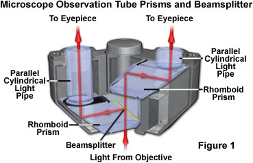
Beamsplitters and prisms are not only found in a wide variety of common optical instruments, such as cameras, binoculars, microscopes, telescopes, periscopes, range finders, and surveying equipment, but also in many sophisticated scientific instruments including interferometers, spectrophotometers, and fluorimeters. Both of these important optical tools are critical for laser applications that require tight control of beam direction to precise tolerances with a minimum of light loss due to scatter or unwanted reflections. Illustrated in Figure 1 is a diagram of a typical binocular microscope observation tube configuration. In order to divert light collected by the objective into both eyepieces, it is first divided by a beamsplitter and then channeled through reflecting prisms into parallel cylindrical optical light pipes. Thus, the binocular observation tube utilizes both prism and beamsplitter technology to direct beams of light having equal intensity into the eyepieces.
Prisms can be roughly divided into three general categories: reflecting prisms, polarizing prisms, and refracting or dispersion prisms. The former are useful for redirecting light beams by total internal reflection while the latter can be employed to bend and separate light into its component colors. In contrast, polarizing prisms are birefringent crystals that divide incident non-polarized light into separate components polarized orthogonally to each other. These prisms are employed to produce polarized light for optical instruments such as microscopes and polarimeters.
Mirrors are commonly utilized to fold the light beam through an optical system. Prisms can also serve an identical function, except that the reflecting internal surfaces of prisms behave as rigidly mounted mirrors with each face having a permanent orientation with respect to all others. This feature is attractive to designers, because once a prism has been constructed, it will retain orientational parameters that do not deviate and require no further adjustment in the final assembly, except for positioning the prism unit itself. Depending upon the entrance angle for a light beam, prisms can refract light or allow it to enter undeviated and undergo total internal reflection, provided the refractive index is sufficient and internal prism angles have the proper geometry.
Reflecting Prisms
The angular parameters displayed by various prism designs cover a wide gamut of geometries that dramatically extend the usefulness of prisms as strategic optical components. Reflecting prisms are often designed to be located in specific orientations where the entrance and exit faces are both parallel and perpendicular to the optical axis. For example, the right-angle prism possesses the simple geometry of a 45-degree right triangle (see Figure 2), and is one of the most commonly used prisms for redirecting light and rotating images. A parallel bundle of light waves entering one of the smaller prism faces (or legs) at a perpendicular angle is reflected from the hypotenuse (longest) face and exits through the other leg. Provided the prism is constructed from a material having a refractive index greater than the square root of 2 (approximately 1.414), the light will undergo total internal reflection at the glass/air boundary while inside the prism.
This feature renders prisms an excellent substitute for mirrors, because there is no requirement for metallic or dielectric coatings on the reflecting surface, which serves as a nearly perfect reflector. The only light scattering and loss that occurs (usually only a few percent) is due to minute surface imperfections, absorption by the prism material, and reflections at the entrance and exit legs of the prism. Careful polishing of the surfaces and the application of a suitable anti-reflection coating to the legs will minimize even these minor light losses. In this orientation, the right-angle prism acts as an image inverting system with the top face performing the duties of a plane mirror by producing left-handed images from right-handed images, and vice versa. Note in Figure 2(a) that the red knob and stub end of the alignment marker has been flipped, but the left and right sides remain in the same position.
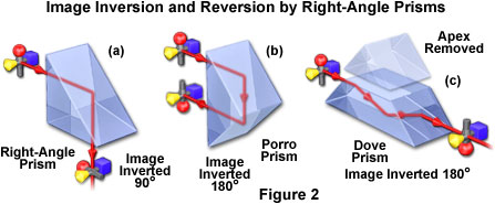
Reorienting the right-angle prism, so that light now enters and exits through the hypotenuse face, produces a non-reversing mirror, as illustrated in Figure 2(b). Often termed a Porro prism, the light beam in this configuration undergoes two internal reflections after it enters the prism and is deviated by 180 degrees upon exiting. As a result, images are inverted top to bottom, but are not reversed right to left. When a prism is utilized in this manner, it is often referred to as a constant deviation prism because the incident and emerging light rays will be parallel, regardless of the angle at which light enters the prism. Porro prisms are often employed in traditional binocular configurations, where they are doubled together orthogonally to first invert and then reverse light beams to produce erect or upright images. The twin prisms fold the light path of an optical system and also displace the image both horizontally and vertically by half the length of the hypotenuse in each direction. Binocular prisms are usually manufactured with rounded corners to reduce weight and size, and have a small slot cut into the hypotenuse face to obstruct light rays that are internally reflected at glancing angles.
A third orientation of the right-angle prism with respect to the incident light beam (Figure 2(c)) is commonly referred to as a dove prism, which is useful as an image rotator. Dove prisms often have the unnecessary triangular apex section removed, both to save weight and to reduce stray internal reflections. A bundle of light rays enters the dove prism parallel to the hypotenuse face, and is refracted downward at the first leg toward the longer internal surface. Upon being totally reflected by the hypotenuse face, the light is then refracted again as it exits the prism through the other leg and proceeds in the same direction that it was traveling before entering the prism. Because the dove prism introduces a substantial amount of astigmatism when convergent light is passed through, it is used almost exclusively with collimated light. The dove prism does not deviate or displace an image, but it can be utilized to either invert or reverse an image.
Right-Angle Prisms
Discover how light reflection and rotation, inversion, and reversion of an image by a right-angle prism changes as a function of the prism orientation with respect to incident light.
Although at first glance the dove prism appears to be a good candidate for dispersion (due to the angular entrance of the light beam), transmission of light through the prism is actually equivalent to passage through a slab of glass with the side benefit of image rotation. An interesting effect of the dove-style geometry results as the prism is rotated along the longitudinal axis. In the orientation presented in Figure 2(c), light passing through the dove prism forms an image that is inverted from top to bottom and reversed from right to left. However, if the prism is rotated 45 degrees, the resulting image is rotated through 90 degrees, and when the prism is rotated another 45 degrees (for a total of 90 degrees, in effect, being placed on its "side"), the image is now rotated by 180 degrees. Thus, the image is rotated twice as fast as the prism. In practice, two dove prisms are often cemented together at the hypotenuse (after placing a mirrored surface on these faces) to produce a bi-prism with the ability to change the direction of sight for telescopes, periscopes, and other optical instruments.
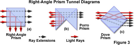
Reflecting prisms can be represented as a plane parallel glass plate or block having a thickness that can be determined by unfolding the prism around its reflecting surfaces, as illustrated in Figure 3. Unfolded prisms are displayed in the form of a tunnel diagram, and have a thickness equal to the length of the entrance and exit faces. Armed with this information, the apparent thickness of a prism can be determined from the refractive index, which is expressed by the equation:
where d is the glass thickness (determined from the unfolded prism), and n is the index of refraction. The unfolded prism paths for simple right-angle and Porro prisms are presented in Figure 3(a) and Figure 3(b), respectively. For a right-angle prism, the unfolded thickness equals the length of the short legs (through which light enters and exits the prism). Unfolding a prism will also demonstrate the maximum beam size that can pass through without spreading past the edges of the prism. A tunnel diagram for the dove prism is illustrated in Figure 3(c), and shows the unfolded path of refracted light rays as they would traverse a glass block tilted with respect to the incident light angle. Note that this configuration is the only prism in Figure 3 that experiences refraction at the incident and exit interfaces. The angular entry of light rays into a dove prism requires that the height of the entrance face be limited by the length of the base (the hypotenuse, or long face). Unfolding the components of an optical system is often the best way to determine how light passes through the various apertures, lenses, and angular deflectors, and can be carefully scrutinized to optimize design parameters and efficiency.
Replacing the hypotenuse face of a right-angle prism by a total internal reflection roof, consisting of two surfaces positioned at 90-degree angles with respect to one another, yields an Amici prism (see Figure 4(b)). Addition of the roof serves to maintain the 90-degree inversion to the image observed with a right-angle prism, but also rotates the image by 180 degrees around the optical axis. At the roof surface, light rays incident at angles that would normally enable them to be transmitted through the hypotenuse face undergo crossover by total internal reflection through the prism. The result is to divide images in the center and transpose the left and right portions. Amici prisms are expensive and difficult to fabricate because the roof angle must be held to a tolerance of 2-4 seconds of arc to avoid producing a double image artifact. In addition, introduction of the roof element degrades diffraction-limited resolution by almost a factor of two in the direction perpendicular to the roof edge, regardless of the accuracy of construction. This artifact can be partially offset by multi-layer coatings applied to the surface.
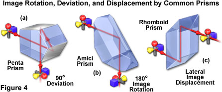
Another common design, the penta prism (Figure 4(a)), deflects light through a constant 90-degree angle without reversing the image (this prism should not be confused with the more complex pentaprism utilized in single-lens reflex cameras, which also uses a roof prism to produce an erect image). As illustrated in Figure 4(a), the penta prism reflects light from two internal surfaces at angles insufficient to undergo total internal reflection, thus requiring thin external mirror coatings. Penta prisms are often referred to as an optical square (as applied to surveying instruments), because the incoming light beam is deviated at the same angle, regardless of the prism orientation with respect to the line of sight. Rhomboid prisms are constructed in the shape of a parallelogram to displace a light beam or the line of sight without affecting the orientation of the image (Figure 4(c)). The prisms have two smaller parallel reflecting surfaces (legs) that are cut at a 45-degree angle to a much longer rectangular-shaped body. A variety of additional prism designs have unique properties, primarily image erecting and inversion, which enable them to perform specific functions in optical systems. For further information, the reader is referred to advanced texts on the subject.
Polarizing Prisms
Scottish physicist William Nicol first devised a polarizing prism in 1828 by cutting a rhombohedral section of the mineral calcite (Iceland spar) diagonally, polishing the cut surfaces, and cementing them back together with Canada balsam. The result is a transparent birefringent crystal, known as a Nicol prism, which effective separates polarized light at the interface between the two crystal halves. Upon entering the prism through one of the smaller angled legs (parallel to the long axis of the crystal), non-polarized light is split into two polarized components, termed the ordinary and extraordinary waves, which traverse the crystal at different speeds. The two separated light waves also have their electric vector vibration directions positioned at a 90-degree angle with respect to one another. When the interface between the two crystal sections is encountered by the separated light waves, the ordinary component is refracted to a much greater degree and is absorbed by a layer of black paint applied to the outer surface of the prism. In contrast, the extraordinary ray passes through the interface and emerges from the prism slightly displaced, but still traveling in a direction that is parallel to the incident light. The resulting plane-polarized light can be utilized to illuminate birefringent specimens in a microscope or any other device that requires the input of light having electric field vibrations restricted to a single plane.
Common variations of the Nicol prism include the Glan-Foucault polarizer (See Figure 5(a)), which consists of two identical prisms of calcite cut with the optical axes parallel to the corner edges, and mounted with a small air gap so that the long crystal faces are parallel to one another. This prism is transparent to wavelengths ranging from about 230 nanometers, in the ultraviolet region of the spectrum, to over 5000-nanometer infrared radiation. Such a broad wavelength transmission range enables Glan-Foucault prisms to be utilized in a variety of instruments. Like the Nicol prism, incident light striking the Glan-Foucault prism is separated into ordinary and extraordinary waves that are vibrating either parallel or perpendicular to the optical axis. However, in this case, the divided light waves travel through the prism without refraction until they encounter the glass/air boundary, whereupon the ordinary ray is totally internally reflected, but the extraordinary ray passes through the boundary with only a slight deviation.
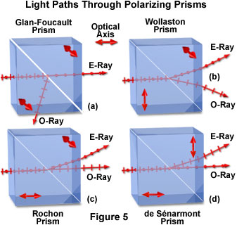
If the crystal halves are cemented together, the prism is then referred to as a Glan-Thompson polarizer (or prism), and can withstand more intense radiation, such as that from a high-intensity laser source. A third birefringent prism is known as the Wollaston prism, which is really a polarizing beamsplitter made from two calcite or quartz sections cemented together with the optical axes oriented orthogonally (Figure 5(b)). Polarized light passing through a Wollaston prism is separated into orthogonal waves, as described above for the other polarizing prisms. However, when the ordinary and extraordinary waves encounter the diagonal cement junction, they exchange identities, are refracted in different directions, and emerge from the prism slightly displaced from one another. The deviation angle (often termed the shear) between the two exiting light waves is determined by the wedge angle of the prism, which is usually varied between 15 and 45 degrees.
Several derivatives of the Glan-style prisms can be produced by altering the orientation of calcite or quartz optical axes with respect to the individual crystal halves (as illustrated in Figure 5). The Rochon prism (Figure 5(c)) positions the axes orthogonally to each other and is arranged so that incident non-polarized light enters the prism parallel to the optical axis (and is not separated). When light waves pass through junction in a Rochon prism, they enter a new region where the optical axis is oriented perpendicular to the waves. This causes the light to be split into ordinary and extraordinary components, with the ordinary wave passing through undeviated and the extraordinary wave being refracted away from the perpendicular. The reverse scenario can be achieved with a Senarmont prism, which also has the axis of the first crystal section oriented parallel to incident illumination. However, when the light waves encounter the boundary in a Senarmont prism (see Figure 5(d)), the orientation of the optical axis in the second half of the prism allows the extraordinary ray to pass through undeviated, but refracts the ordinary wave. These prisms can be utilized to select individual orientations of polarized light for specific optical applications.
Refracting or Dispersing Prisms
The first demonstration of refraction and dispersion in a triangular prism was performed by British physicist Sir Isaac Newton in the late 1600s. Newton showed that white light could be dissected into its component colors by an isosceles prism having equal sides and angles. In general, a refracting or dispersing prism has two or more plane surfaces that are oriented in a manner favorable to refraction rather than reflection of incident light beams. When a light ray strikes the surface of a dispersing prism, it is refracted upon entering according to Snell's law and then passes through the glass until the second interface is reached. Once again, the light ray is refracted and emerges from the prism along a new path (see Figure 6). Because the prism alters the propagation direction of light, waves passing through a prism are said to be deviated by a specific angle, which can be very precisely determined by applying Snell's law to the geometry of the prism. The deviation angle is minimized when the light wave enters the prism with an angle that allows the beam to traverse through the glass in a direction parallel to the base.
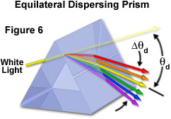
The amount of light deviation produced by a prism is a function of the incident angle, the prism apex (top) angle, and the refractive index of the material from which the prism is constructed. As prism refractive index values are increased, so is the deviation angle of light passing through the prism. Refractive index is often dependent upon the wavelength of light, with shorter wavelengths (blue light) being refracted at greater angles than longer wavelengths (red light). This variation of the deviation angle with wavelength is referred to as dispersion, and is responsible for the phenomenon that Newton observed over 300 years ago.
Refraction by an Equilateral Prism
Discover how the incident angle of white light entering the prism affects the degree of dispersion and the angles of light exiting the prism. The tutorial also explores how changes in refractive index affect dispersion of light passing through the prism
Dispersion can be fine-tuned by selecting glasses with the appropriate refractive index characteristics for a particular application. In general, the dispersion properties of various glass formulations are compared through Abbe numbers, which are determined by measuring the refractive indices of specific reference wavelengths passed through the glass. Abbe numbers for popular glasses utilized in prism construction are listed in Table 1. As is evident from examining the table, lower Abbe numbers refer to higher dispersive power, translating into a greater angular spread of colors in the emerging light spectrum.
Abbe Numbers and Refractive Indices of Prism Glasses
| Glass Formula | Refractive Index | Abbe Number |
|---|---|---|
| Fused Quartz | 1.4585 | 67.8 |
| BK 7 | 1.5168 | 64.17 |
| Light Barium Crown | 1.5411 | 59.9 |
| Light Flint | 1.5725 | 42.5 |
| Dense Flint Glass | 1.620 | 36.37 |
| Extra Dense Flint Glass | 1.6725 | 32.20 |
| Very Dense Flint Glass | 1.728 | 28.41 |
Table 1
The principal application for dispersing prisms is to separate wavelengths in the field of spectroscopy, which is concerned with the study and analysis of spectra. Although prisms were once the optical component of choice for spectrometers and spectrophotometers, diffraction gratings now command a leading role in these instruments. Gratings produce linear dispersion of white light rather than the complex angle versus wavelength relationship exhibited by prisms. However, prisms do have several advantages over gratings, including their enhanced power-handling capabilities, absence of unwanted higher order diffraction phenomena, and lower stray light.
Prism Materials and Manufacturing
In order for a prism to perform at the required specifications, it should be manufactured from the correct glass formulation and be free from strain and internal defects. All surfaces of the prism must be perfectly flat and ground to precise angles (although the angles in some prisms are far more critical than others) deviating no more than 5 to 10 minutes for general use, but held to just a few seconds for critical applications, such as roof prisms. Excess material at the corners is usually removed or chamfered in order to reduce chipping and cracking and to minimize the weight and size of the prism. External surfaces should be kept clean to the most exacting optical standards, which can be accomplished by applying a coat of lacquer or by silvering the surface where appropriate. In many instances, notches are milled across the surface to suppress ghost images produced by stray internal reflections.
Variations in glass density within the prism material can produce image distortion and alter dispersion characteristics of the glass. In a similar manner, bubbles or foreign debris in the glass can produce diffraction artifacts and reduce light transmission. Glasses chosen for prism construction are characterized by their refractive index, dispersion, and light transmission properties.
Beamsplitters
A beamsplitter is a common optical component that partially transmits and partially reflects an incident light beam, usually in unequal proportions. In addition to the task of dividing light, beamsplitters can be employed to recombine two separate light beams or images into a single path. The simplest configuration for a beamsplitter is an uncoated flat glass plate (such as a microscope slide), which has an average surface reflectance of about 4 percent. When placed at a 45-degree angle, the plate will transmit most of the light, but reflect a small amount at a 90-degree angle to the incident beam. Plate beamsplitters are, as the name implies, optical crown glass plates having a partially silvered coating designed to produce a desired transmission-to-reflection ratio. These ratios usually vary between 50:50 and 20:80, depending upon the application.
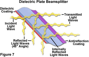
In general, a metallic or dielectric film is deposited on the first surface (facing the incident illumination) of the beamsplitter plate, while an antireflection coating is applied to the back (see Figure 7). Antireflection coatings can be chosen to match the incident angle of light in order to minimize the amount of light reflected from the rear surface of the plate and reduce the possibility of ghost images. Typical antireflection coatings display only about 0.5 percent reflectivity at an incident angle of 45 degrees. Dielectric coatings must also be fine-tuned to produce the proper reflectance, polarization properties, and wavelength distribution at the angle for which the beamsplitter is designed. Because both dielectric and antireflection coatings have negligible absorbance in the visible light region (typically 0.5 percent for a 50/50 beamsplitter at 45 degrees), plate beamsplitters are ideal for a wide spectrum of applications.
One of the most serious consequences of using dielectric coatings for beamsplitter fabrication is the unequal transmission and reflection for p and s (parallel and perpendicular) polarization components of non-polarized incident light beams. As a result, some dielectric beamsplitters divide light unequally according to the polarization content, which can be undesirable in many applications. When using dielectric coatings, this artifact can often be circumvented by altering the polarization vector orientation of the incident light. In addition, the polarization effect can be reduced through the utilization of more sophisticated multi-layer thin-film dielectric coating designs, but often at the expense of other performance aspects.
Specialized non-polarizing beamsplitter coatings have been designed for use with polarized laser light where the incident radiation must maintain its polarization direction in both the transmitted and reflected beams. The coatings can effectively produce a clean 50/50 split of laser energy, regardless of the polarization state of the incident beam. As a side advantage, non-polarized light incident on these coatings has both the parallel and perpendicular components transmitted at almost equal ratios. Plate beamsplitters can also be designed to act as longpass and shortpass edge filters (when positioned at a 45-degree angle) for applications requiring specific wavelength selection. In the case of longpass filters, longer wavelengths are transmitted and shorter wavelengths reflected at a 90-degree angle to the incident beam. Shortpass filters act in a reverse manner (transmit short wavelengths and reflect long wavelengths). Beamsplitters acting as edge filters are often referred to as dichroic or dichromatic mirrors.
Cube beamsplitters are fabricated by cementing together the hypotenuse faces of a matched pair of right-angle prisms with a partially reflecting film deposited onto the face of one the prisms (Figure 8(a)). All four faces of a cube beamsplitter are treated with an antireflection coating to minimize ghost images. For optimum results, the incident light beam should enter the beamsplitter through the prism that has been coated with reflecting film so that reflection occurs before the beam encounters the optical cement used to glue the cube together. Cube beamsplitters are more resistant to mechanical damage and deformation than plate beamsplitters, primarily because the reflective surface is protected by being sandwiched between the glass prisms.
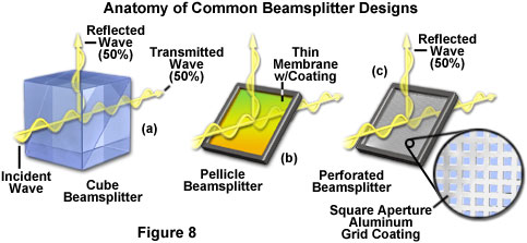
Plate beamsplitters have some advantages when compared to cube beamsplitters, primarily the lack of an optical cement in the vicinity of the dielectric or metallic film, which can absorb light energy and reduce transmission. As a consequence, plate beamsplitters can withstand significantly higher levels of radiation without suffering damage. Single glass plates are also much smaller and lighter than a twin-prism cube, and can be more easily fitted into tight spaces for compact optical configurations.
Advanced coatings for cube beamsplitters include hybrid metal-dielectric films that combine the benefits of both materials. The result is a moderately efficient broadband beamsplitter that typically has absorption levels of about 10 percent with very little polarization sensitivity. Absorption losses are almost equally divided between transmitted and reflected beams, and polarization components lie within 5 to 10 percent of each other. Other broadband coatings have lower absorption characteristics, but are extremely polarization sensitive. All-dielectric non-polarizing coatings are designed for high performance at specific wavelengths, usually for laser applications.
A third important class of beamsplitters is fabricated from a high tensile strength elastic membrane (such as nitrocellulose) stretched like a canvas over a black anodized flat metal frame. Termed a pellicle beamsplitter (Figure 8(b)), the membrane thickness ranges between 2 and 10 micrometers, so thin that it virtual eliminates ghost images. In addition, optical aberrations, such as chromatic, spherical, and astigmatism are reduced to a minimum when compared to plate and cube beamsplitters, dramatically expanding the possibilities of using both convergent and divergent light. Uncoated pellicle membranes transmit about 92 percent of incident light throughout the visible and near-infrared spectral regions, but usually exhibit unacceptable absorbance in the ultraviolet. For most applications, pellicle membranes are coated with a thin dielectric film on the membrane side facing the incident light beam. These beamsplitters often fall victim to interference artifacts that result from the close proximity of the membrane surfaces, and they can also be subject to acoustical vibrations. Pellicle membrane surfaces should not be touched and can be cleaned only by a gentle flow of air.
Perforated beamsplitters (often termed polka-dot beamsplitters; see Figure 8(c)) are fabricated by coating an optical glass substrate with a thin layer of aluminum in fixed-size square apertures. The resulting surface has a "polka-dot" appearance, thus the name. By carefully adjusting aperture size, the ratio of coated to uncoated surface area in a perforated beamsplitter can be manipulated to equally split incident beams into transmitted and reflected components. Light waves encountering the uncoated surface pass through (losing a few percentage points to reflections from the glass) while those impacting the aluminum coating are reflected (usually by 45 degree angles). Perforated beamsplitters demonstrate negligible sensitivity over a wide range of angles, and are useful for splitting light beams from divergent, broadband radiant sources such as a mercury arc or tungsten-halogen lamps. In addition, the grid pattern displays insignificant divergence of the transmitted beam due to diffraction and does not suffer from polarization artifacts. These filters are also useful with deuterium and xenon lamps, and find applications in monochromators, spectrophotometers, and other optical systems.
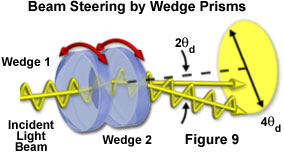
Circular prisms having plane surfaces positioned at slight angles with respect to each other are termed optical wedges, and deflect light by refraction rather than reflection. Although wedges are prismatic in nature, they can be manipulated to act as beamsplitters or beam steerers. The angle at which a wedge diverts incident light depends on the angle between the entrance and exit faces and the refractive index of the glass utilized to manufacture the plate. Wedge angles range between 2 and 25 degrees and have corresponding diopter powers between 2 and 20 centimeters deviation of the refracted light beam per meter of distance from the prism. The direction of light refracted after passing through the wedge can be controlled by rotating the circular prism (see Figure 9). In many cases, two wedges are paired and the light path is altered to an even greater degree over a 360-degree range by rotating the wedges in opposite directions. Wedge prisms act as versatile beamsplitters to prevent ghost images and to steer light beams through adjustable pathways in optical systems.
Both prisms and beamsplitters are important components in microscope observation tubes, where they act to steer light from the objective to the eyepieces or a camera port. In modern microscopes equipped with binocular eyepiece tubes, prisms are also utilized to change the line of sight direction from vertical to a more convenient 45-degree angle. Dichromatic beamsplitter mirrors are also important in fluorescence microscopy to provide excitation illumination for the specimen and to allow secondary fluorescence to enter the eyepieces while blocking reflected excitation wavelengths. Other optical instruments, such as telescopes, spotting scopes, and surveying transits also rely on prisms and beamsplitters to perform their functions.


