Laser Systems for Confocal Microscopy
The lasers commonly employed in laser scanning confocal microscopy are high-intensity monochromatic light sources, which are useful as tools for a variety of techniques including optical trapping, lifetime imaging studies, photobleaching recovery, and total internal reflection fluorescence (TIRF). In addition, lasers are also the most common light source for scanning confocal fluorescence microscopy, and have been utilized, although less frequently, in conventional widefield fluorescence investigations.
Lasers emit intense packets of monochromatic light that are coherent, meaning the laser light is in phase in space and time, and can be collimated, or narrowed, to form a tight beam with a very low rate of expansion. Compared to other light sources, the extremely pure wavelength ranges emitted by the laser have a bandwidth and phase relationship that is unparalleled by tungsten-halogen lamps, arc-discharge lamps, or LED light engines. As a result, laser light beams can travel over long distances and can be expanded to fill apertures or focused to a very small spot with a high level of brightness. Beyond the similarities common to all lasers, which include a gain medium (light source), excitation source (power supply), and electrical resonator, these light sources differ radically in size, cost, output power, beam quality, power consumption, and operating life.
The coherence of monochromatic light produced by most laser systems introduces problems in the application of these light sources for classical widefield microscopy. Light scattering and diffraction patterns are introduced by interference at every surface in the optical path. In addition, the field and aperture diaphragms, as well as dirt, also produce artifacts. These undesirable effects can be minimized or eliminated by a variety of techniques. The most common methods include temporally scrambling laser light by rapidly varying the optical path length between the light source and the microscope, or scanning the specimen point by point as is the case in confocal microscopy systems. In addition, interference and other artifacts can often be eliminated by this aperture scanning technique. If the path length or coherence state of the laser beam fluctuates at a faster interval than the detector integration time (in effect, the video frame rate), the speckle and scattering artifacts disappear from the image.
A successful technique employed by some investigators to improve differential interference contrast (DIC) images produced with an argon ion laser light source is to position a circular glass wedge, spinning at 2500 revolutions per minute, in the light path. Rapid variations in optical path length are introduced by differences in wedge thickness as the wedge rotates in front of the expanded laser beam. Currently, path length variation is usually accomplished by employing a fiber-optic light pipe to route the light between the light source and the microscope. Vibrating the fiber produces continual changes in the optical path length, causing the beam to become temporally incoherent at frequencies below that of the vibration level. The vibrations may be generated by a piezoelectric device, a loudspeaker, or the cooling fan utilized in the laser head.
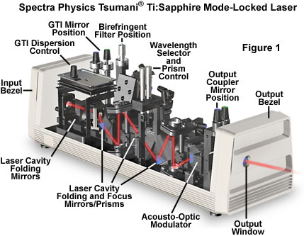
Illustrated in Figure 1 is a self-mode-locked Ti:sapphire pulsed laser, which is currently one of the preferred laser excitation sources in a majority of multiphoton fluorescence microscopy investigations. Ti:sapphire mode-locked lasers provide a large wavelength tuning range, from about 690 to over 1050 nanometers, with pulse widths of approximately 100 femtoseconds in length. In addition, these lasers have sufficient power (greater than 100 milliwatts throughout the tuning range) for the saturation of two-photon excitation in most fluorophores. To ensure proper cooling and humidity control of the laser crystal, nitrogen gas is pumped into the sealed laser head, which is maintained at constant temperature by an external chiller.
The light produced by many laser systems is linearly polarized, with a polarization vector oriented vertically. This property can be exploited in applications requiring a polarized illumination source, such as differential interference contrast, polarized light measurements, or quantitative investigations of fluorescence polarization anisotropy.
The coherence and polarization characteristics of a laser beam are measured by the distribution of light in the beam cross-section, or profile, which changes with increasing distance from the exit mirror of the laser. The following discussion of laser beam characteristics is presented as a general overview of the subject that may prove useful in employing lasers in microscope imaging, laser trapping, and other applications.
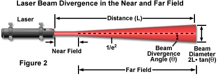
When a laser operates in the simplest transverse electromagnetic mode, referred to as the TEM(00) mode, the emitted beam has a planar wave front and a Gaussian intensity (irradiance) profile. The laser beam diameter is commonly defined as the value at which the intensity has fallen to e(E-2) (13.5 percent) of its peak value. The Gaussian profile of the laser beam arises because of diffraction, which prevents the propagation of a perfectly collimated beam and induces transverse spreading of the light waves. Near the laser output aperture (termed the near field), the phase fronts of the beam can become disordered. As a consequence, the beam cross-sectional shape, size, and irradiance profile then change rapidly with distance from the laser. At greater distances (the far field), the phase fronts stabilize into the resultant Gaussian profile. In some literature references, the near field and far field are referred to by the alternative terms of Fresnel zone and Fraunhofer zone, respectively. The near field is also sometimes termed the Rayleigh range. The far field begins at a distance z defined by
z = A02/λ
where A(0) is the beam diameter at the exit aperture and λ is the wavelength of light emitted by the laser. Applying this equation to an argon laser emitting a 0.6-millimeter-waist-diameter beam at a wavelength of 488 nanometers, the far field begins at approximately 74 centimeters from the exit aperture.
Presented in Figure 2 is a schematic diagram of laser beam geometry and divergence in the near and far fields. As discussed above, the beam can be considered essentially a parallel bundle of wavefronts that undergoes little spreading in the near field. Beyond the near field, the beam divergence angle (θ), which is measured from the center of the beam to the edge (e(E-2)), grows larger and becomes the critical parameter in determining beam diameter (D) according to the equation:
Beam Diameter (D) = 2L • tan(θ)
where D is the variable signifying laser beam diameter and L represents the length of the distance from the laser exit aperture to the measurement point on the beam. In practice, several laser beam characteristics, including the irradiance profile, are critical factors in many microscopy applications, and knowledge of the distance to the far field may be necessary in configuring the imaging system. Table 1 presents calculated values of this distance (using the equation given above) for a number of commonly used lasers and emission lines and typical beam waist diameters.
Distance to the Far Field
Table 1
| Compound | Solvent | Excitation
Wavelength (nm) | Emission
Wavelength (nm) | Quantum Yield |
|---|---|---|---|---|
| Acridine Orange | Ethanol | 493 | 535 | 0.46 |
| Benzene | Ethanol | 248 | 300-350 | 0.04 |
| Chlorophyll-A | Ethanol | 440 | 685 | 0.23 |
| Eosin | Water | 521 | 544 | 0.16 |
| Fluorescein | Water | 437 | 515 | 0.92 |
| Rhodamine-B | Ethanol | 555 | 627 | 0.97 |
Whether or not the beam exhibits Gaussian character is important in most laser applications because the beam often has to be focused, shaped, and otherwise modified by lenses and other optical components. A Gaussian beam has certain definable transformation characteristics, and these enable assumptions to be made about how the beam will propagate through an optical system.
The angular radius (or beam divergence angle; see Figure 2), designated by θ (in radians), of a Gaussian beam in the far field is approximated by the expression:
θ = λ /πa0
where a(0) is the beam waist radius at the laser exit aperture. The beam waist diameter is a function of laser wavelength, cavity length, and other design parameters of the cavity. As the distance (z) from the laser increases, the beam waist radius is given by the equation:
a(z) = θz
Typically, laser beams are characterized by beam propagation parameters such as the square of M, or K (which is equivalent to the reciprocal of the square of M), determined from a combination of near field and far field measurements as follows:
M2= πA0θ/4λ
Smaller values of M2, which is termed a propagation constant or propagation factor, are indicative of higher beam quality, particularly in reference to a smaller diameter and divergence. The factor describes the relationship of the real beam to that of an ideal Gaussian beam.
Coherent Gaussian beams have specific properties that cause them to differ from incoherent light beams in their propagation and transformation by lenses and mirrors. In the case of a diffraction-limited beam, the intensity profile of a Gaussian beam is itself Gaussian, provided that the beam is not truncated by the lens aperture. When the Gaussian beam diameter is one-half the aperture diameter of the lens, the intensity profile of the emergent beam remains Gaussian. When the Gaussian beam diameter is equal to the diameter of the lens aperture, the output beam intensity profile is a mixture of the Gaussian function and that of an Airy disk. Finally, a Gaussian beam diameter significantly larger than the diameter of the lens aperture produces the output profile of an Airy disk. In the latter instance, much of the laser power may be lost due to overfilling of the lens entrance aperture.
The overall topic of Gaussian beam optics is thoroughly covered in numerous textbooks, and details not discussed here may be obtained from more comprehensive sources. Two types of manipulation of the Gaussian beam are of particular interest to the microscopist utilizing lasers, beam concentration and beam expansion.
When a laser beam is focused to a very small spot by an aberration-free microscope objective (beam concentration), the radius of the spot at the focus (at distance z) is given by the expressions:
a(z) = λf/πa0
where f is the focal length of the lens. As an example, if a 100X objective with a numerical aperture of 1.3 (producing a focal length of approximately 1.6 millimeters) is employed to concentrate the 488-nanometer beam of an argon laser having a 0.3-millimeter radius, the focused spot radius (determined from the previous equation) is 0.8 micrometers. Increasing the beam waist fivefold through beam expansion (as discussed below) would result in a focused spot radius of approximately 0.16 micrometers.
It is important to note that extremely high power densities are achieved at the focal point of a concentrated laser beam. A 10-milliwatt beam focused to a diffraction-limited spot 0.22 micrometers in diameter results in a power density of approximately 30-million watts per square centimeter. Such high energy levels can rapidly degrade or destroy lens and filter coatings, as well as introduce considerable photochemical damage to biological specimens. However, for such a minute spot size, diffusion of thermal energy can be so effective in water that a high-energy, near-infrared beam may do little damage to a biological specimen unless absorption of the energy by the specimen is sufficiently high.
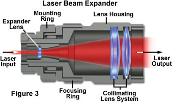
In many applications of lasers in optical microscopy, the laser beam is initially expanded by the use of a Keplerian or Galilean beam expander, which are actually reversed telescopes (typical laser beam expander anatomical features are illustrated in Figure 3). The divergence of a coherent Gaussian beam can be reduced, and the beam optimally collimated over a longer distance, if the laser beam is first expanded. Referring to the previous equations, the angular radius of the beam, designated θ, is inversely proportional to the beam waist radius, a(0), at the laser exit aperture. Therefore, expanding the beam waist radius diminishes the divergence proportionally.
It is practical for many applications in microscopy to pipe the laser output directly into the microscope optical path through a flexible optical fiber (as illustrated in Figure 4). This technique is preferable to the alternative method of rigidly aligning the laser and microscope, which requires employing a massive, vibration-free optical table and numerous fixed mirrors and other components
When a laser beam is focused by a lens onto an optical fiber, the coupling efficiency and characteristics of the beam that emerges from the fiber depend heavily on the fiber geometry. Most of the optical fibers used for laser light delivery are constructed with a fused-silica core. These fibers consist of an inner core fabricated with high-refractive-index silica and surrounded by a sleeve, termed the cladding, composed of lower-refractive-index material. Light is prevented from escaping the fiber along its length by total internal reflection at the interface of the core and the cladding. The cladding may be composed of silica, glass, a hard fluoropolymer, or a soft silicone.
Optical fibers are classified as single-mode or multimode according to the diameter of their inner cores. A single-mode fiber allows propagation of only the lowest-order mode at one particular wavelength (Figure 4). The wavelength propagated and polarization preservation of the wave are determined by the fiber diameter. Although other wavelengths may propagate, they do so with reduced efficiency. Typical single-mode fiber diameters range from 3 to 6 micrometers for visible-light wavelengths, and the output irradiance profile of a single-mode fiber is Gaussian.
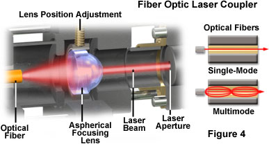
A multimode optical fiber enables the propagation of more than one mode, and is not restricted to a single wavelength. The inner cores of multimode optical fibers are larger than single-mode fibers, ranging from approximately 100 micrometers to 1.2 millimeters in diameter. The output irradiance profile from a multimode fiber has a flat shape, referred to as a top-hat profile, with a numerical aperture that is determined by the core and cladding refractive indices.
The acceptance cone angle, θ, of the fiber core is related to the numerical aperture, NA, of the fiber as follows:
NA = sin θ/(n2core - n2cladding)1/2
where n represents refractive index. Efficient coupling of laser light to the fiber core occurs when the fiber core numerical aperture and that of the beam concentration lens are matched. The efficiency of light transmission through an optical fiber is typically as high as approximately 90 percent, but may be sharply reduced (to only 60 or 70 percent) by bends having very small radii (less than 3 centimeters).
In using any laser, it is crucial not only to prevent any direct or specularly reflected laser light from entering an observer's eyes, but also to avoid reflection of the beam from a component of the optical system back into the laser system. The former is an obvious personal safety precaution, while the latter caution is important to prevent an additional reflector from returning a coherent beam back into the laser, causing possible damage to the system.
Stability of the laser light source is an important aspect in many applications, particularly in quantitative microscopy, where illumination intensity fluctuations can adversely affect experimental results. A number of factors related to stimulated emission and cavity length fluctuations can induce frequency noise in the output beam, but other perturbations causing amplitude fluctuations can create both high-frequency intensity noise and slow variations (drift) in optical output power. Some sources of these intensity fluctuations are related to the function of the laser head itself or the power supply. The most common sources of noise in the output beam for various laser categories are listed below:
- Gas lasers - Mirror misalignments from resonator vibrations, noise from optical pump sources, plasma oscillations and instabilities of the ion discharge process, fluctuations in power supply current, microphonics from cooling water turbulence, and fan-induced noise in forced-air cooling systems are all potential noise sources.
- Solid-state lasers - Noise sources include microphonics, pump source fluctuations for both lamp and diode pumps, cavity alignment errors, and the random frequency-related noise (termed 1/f noise) that is related to thermal fluctuations in the laser medium.
- Dye lasers - Both noise (high frequency) and drift result from density inhomogeneity and air bubbles in the dye solution, and by dye pump and laser pump source instabilities.
- Semiconductor (diode) lasers - Noise can result from fluctuations in the drive (bias) current or temperature, and 1/f noise is caused by trapping of carriers in the junction and by other types of carrier (electron hole) recombination effects.
All lasers are susceptible to noise introduced by their power supplies. Switching power supplies, which have become common because of their efficiency and small size, are particularly likely to introduce ripples into the laser system at frequencies ranging into the tens of kilohertz. Such interference, when it affects the light beam in optical microscopy systems, can be especially troublesome to diagnose and remove. The primary difficulty is due to the similarity with noise introduced into the system by other sources, such as electromagnetic fields in the laboratory environment. To achieve adequate output stability, semiconductor lasers must be operated with diode current supplies having the highest electrical stability and lowest noise available, and with precise temperature control. Other external noise sources must be controlled, including dust in the laboratory and vibrations originating from local traffic and building equipment.
The beam intensity of continuous wave (cw) lasers can be stabilized by either electronically controlling the tube current or using external components that modulate the light intensity. Two different methods are often employed to control the tube drive current. In the constant current mode, tube current is directly controlled by an electronic feedback loop to minimize fluctuations. Because the laser output is also temperature dependent, this type of control circuit is most effective if adequate temperature control is provided. Constant output power stabilizing systems operate by controlling the drive current in response to a signal derived from a circuit that samples the output beam using a beamsplitter and photodiode monitor. This physical arrangement is applicable for gas lasers and several other geometries, but smaller diode lasers are commonly assembled in a package that already includes an integral photodiode. The monitor photodiode samples emission from the rear facet of the laser wafer and produces a signal that enables feedback control of the output power.
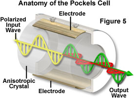
External components used to stabilize laser intensity generally employ a fast feedback system to control an electro-optic modulator that minimizes fluctuations in beam power. The external Pockels cell modulator (see Figure 5) is available from a number of manufacturers, and can be used, in principle, to stabilize the output power of any continuous wave laser. Large intensity fluctuations (up to approximately 50 percent) can be corrected by this technique, but with a proportional reduction in total output power. A wide range of correction capability is important with many systems. The helium-cadmium laser, for example, can exhibit variation in output power of around 20 percent, due in part to strong plasma oscillation between certain beam frequencies. Systems exist that are reported to be suitable for regulating cw and mode-locked lasers to within a few hundredths of a percent of their output power, and over a frequency range from direct current to several hundred megahertz, with noise attenuation of 500:1 or greater.
The basic components of a Pockels cell modulator are presented in Figure 5. External devices for regulating laser output intensity, similar to the design illustrated in Figure 5, are sometimes categorized or marketed under the term noise eaters. The fundamental concept behind electro-optic modulators using the Pockels effect is based on a mechanism for varying the polarization properties of the cell at an extremely rapid rate to provide a variable beam attenuator for control of laser intensity. The polarization state of the laser output determines the total attenuation of the modulator, but up to 80 percent transmission is possible. Following emission from the laser head, a portion of the beam is diverted by a beamsplitter to a photodiode, which compares the intensity to a preset (selectable) reference intensity, and amplifies the difference signal so that it can drive the electro-optic Pockels cell modulator. The amplified signal produces a refractive index change in the cell that rotates the plane of polarization, thereby varying the beam attenuation in proportion to the difference voltage that is applied. Among substances that exhibit a change in polarization properties with changes in electric field (Pockels effect) are potassium dihydrogen phosphate and lithium niobate, and crystals of these materials are commonly utilized in the beam modulators.
In situations where randomly polarized light is stabilized by a Pockels cell system, the modulator must be positioned between crossed polarizers, and further consideration is necessary to minimize the effects of these additional components on the beam stability. Because dust, vibrations, and other interferences can alter beam stability at any point in the optical path, it is important that external stabilizers are placed as close as possible to the specimen position in optical microscopy systems. This effort will help ensure that the most stable beam is delivered to the specimen.
Diode lasers, semiconductor devices that have been under development for decades, are now available with sufficient output power to be of interest to microscopists. Diode lasers are available in a range of wavelengths spanning from the ultraviolet to the near infrared, with output power substantial enough for confocal microscopy applications. In addition, those diode lasers exhibit improved beam shape and stability, which has enabled them to replace gas lasers in practically all applications. Diode lasers typically have a lifespan ranging between 10,000 and 50,000 hours, but are extremely sensitive to electrostatic shock, so they must be handled carefully.
Of great interest to optical microscopists is the development of tunable diode lasers, which can compete in terms of power and versatility with tunable dye lasers and Ti:sapphire lasers (discussed below and illustrated in Figure 1). Tunable dye lasers have a wavelength range of 600 to 1800 nanometers and can deliver 5 to 25 milliwatts of power. They have the advantages of relatively low cost, compact size, long lifetime, and low heat production, eliminating the requirement for external cooling systems.
Diode-pumped solid-state lasers (DPSS) utilize a diode laser instead of noble gases, arc lamps, or flashlamps to pump the solid-state lasing material. The power output, beam quality, and stability exhibited by diode-pumped lasers approaches that of a gas (helium-neon) laser, but the efficiency and size are more comparable with diode lasers. Typical operating and maintenance costs of diode-pumped lasers is less than that of gas lasers, and most systems are cooled either by convection or forced air.
Diode-pumped neodymium-yttrium aluminum garnet (Nd:YAG) lasers generate 1064-nanometer light in the milliwatt power range. Frequency doubling leads to a compact device with a continuous-wave output at 532 nanometers, and frequency tripling can also be employed to generate a pulsed output at 355 nanometers. The tightly folded resonator (TFR) was developed for pumping a crystal of neodymium-yttrium lithium fluoride (Nd:YLF) with high power and efficiency, using an array of diode lasers to generate several watts of power at 1047 nanometers. Frequency doubling, tripling, and quadrupling in this type of laser results in power outputs of up to hundreds of milliwatts of coherent light at 523, 349, and 262 nanometers (second, third, and fourth harmonics). Other advantages of diode lasers as pump sources include an extended lifetime (typically more than 5000 hours, compared to a few hundred hours for lamps), a collimated and easily focused output that matches the small lasing volume of the solid-state laser, and greatly reduced thermal loading of the laser rod, which usually requires water cooling when halogen arc lamps are used as pumps.
Development of diode-pumped solid-state lasers has been driven by industrial and commercial applications requiring high power (generally several watts) in the green (532 or 523 nanometers) and ultraviolet (355 or 349 nanometers, and the fourth harmonic at 266 nanometers) wavelength ranges. Output in the ultraviolet spectral region is pulsed, with energies ranging from 100 microjoules to 10 millijoules, pulse durations in the nanosecond range, and repetition rates as high as 10 kHz. These lasers are very useful in microscopy for triggering the release of caged compounds. The pulse repetition rates, however, are still too slow for use as an illumination source for most confocal microscopy applications.
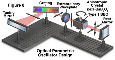
Further development has led to the combination of diode-pumped solid-state lasers with optical parametricoscillators (OPOs; see Figure 8) to produce a tunable, pulsed output that is continuously variable from 205 nanometers to 2000 nanometers. Although the initially available systems have been expensive and complex in operation, scaled-down versions more suitable for use in microscopy have been introduced.
Titanium-doped sapphire lasers (commonly known as Ti:sapphire lasers, see Figure 1) provide the advantages of tunability for pulsed and continuous light delivery, as well as solid-state dependability. These lasers can deliver very short light pulses (approximately 80 to 100 femtoseconds) at high repetition rates (100MHz). The range of tunable wavelengths extends from the far red to the near-infrared spectral regions (700 to 1000 nanometers). Most of these lasers are operated with optical pumping by high-power argon lasers, as well as requiring water cooling. As a result of the expense and complexity involved with operating and maintaining Ti:sapphire lasers, their use has been limited primarily to multiphoton microscopy.
Conclusions
Among the major differences between multiphoton and confocal laser fluorescence microscopy is the type of laser used in these often complementary techniques. Lasers for multiphoton microscopy are considerably more expensive and difficult to operate than the small air-cooled lasers employed in confocal microscopy.
Present applications of lasers in microscopy are expanding rapidly in the areas of confocal microscopy, optical trapping, and the release of caged compounds and fluorophores. The development of compact solid-state lasers with emission lines across the spectrum should serve to further increase the utilization of these devices in microscopy.
Sorry, this page is not
available in your country.


