Magnification with a Bi-Convex Lens
Magnification with a Bi-Convex Lens - Java Tutorial
Single lenses capable of forming images (like the bi-convex lens) are useful in tools designed for simple magnification applications, such as magnifying glasses, eyeglasses, single-lens cameras, loupes, viewfinders, and contact lenses. This interactive tutorial explores how a simple bi-convex lens can be used to magnify an image.
The tutorial initializes with the lens performing a 1:1 magnification, where the giraffe is positioned at two times the focal length (to the left of the lens) and the real, inverted image is also located at twice the focal length from the lens on the image size. In order to operate the tutorial, use the mouse cursor to drag the lens to the left (to increase magnification) or right (to decrease magnification). As the lens is translated to the left (and closer to the giraffe), the image of the giraffe (on the right side of the lens) increases in size. As the lens is moved away from the giraffe, the image of the giraffe decreases in size until, at infinite distance (when the lens is at the far right), only a tiny image of the giraffe appears in the focal plane.
Traces of light rays passing through a simple bi-convex thin glass lens are presented in Figure 1, along with the other important geometric parameters necessary in forming a focused image by the rays. The focal points of the lens are denoted by the variable F, and there are two separate focal points, one in front of the lens (on the left-hand side of Figure 1) and one behind the lens (on the right). The principal planes of the lens are denoted by dashed lines, and the distance between each principal plane and its respective focal point represents the focal length (f). Because the bi-convex lens illustrated in Figure 1 is symmetrical, the principal planes are located equal distances from the lens surfaces, and the front and rear focal lengths are also equal.
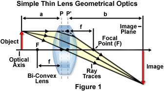
The object (or specimen) being imaged by the lens is positioned in the object plane, located on the left-hand side of the lens by convention, and is represented by a red arrow that travels upward from the optical axis, which passes through the center of the lens, perpendicular to the principal planes. Ray traces through the lens (yellow arrows) emanate from the object and proceed from left to right through the lens for form a magnified real image (inverted red arrow) in the image plane on the right-hand side of the lens. The distance between the front principal plane of the lens and the specimen is known as the object distance, and is represented by the variable a in Figure 1. In a similar manner, the distance from the rear principal plane to the image (the variable b in Figure 1) is termed the image distance. These parameters are the fundamental elements defining the geometrical optics of a simple lens and can be used to calculate important properties of the lens, including focal length and magnification factor.
Sorry, this page is not
available in your country.


