What to Consider When Choosing a Microscope Camera
Thanks to recent advances in technology, there are many interesting microscopy-dedicated cameras available on the market. Here, we summarize the current methods and technologies used by these cameras as a guideline for achieving high-quality images and maximizing the benefits of the latest techniques for your observations and experiments.
Key Elements of Image Quality
The most important factor in ensuring successful microscopic imaging is choosing the appropriate optics and camera for your application. For example, an sCMOS (scientific complementary metal-oxide semiconductor) camera is a great choice for most fluorescence imaging but unsuitable for long-exposure applications, such as bioluminescence imaging. The following sections detail the major elements to consider regarding microscope camera capabilities and advantages according to the application.
Resolution: Microscopes can be used to observe tiny structures that are difficult to resolve optically. These optical limitations mean that a higher number of pixels or smaller pixel pitch does not always provide higher resolution. The key to achieving better resolution is to select the proper pixel pitch in relation to the numerical aperture (NA), the total magnification of the optical system, and the sample’s spatial frequency. Fig.1 is a schematic of the modulation transfer function (MTF) demonstrating the response of an imaging system with a 500 nm light and 5 µm pixel pitch. Fig.1(a) indicates that the sensor’s Nyquist frequency, which is half of the sampling frequency or the reciprocal of the pixel pitch of the sensor, is lower than the optical cutoff frequency, which is defined in Eq.1. In this case, it is worth trying a smaller pixel pitch to achieve higher resolution. On the other hand, in the case of Fig.1(b) and (c), a smaller pixel sensor cannot provide higher resolution because the light from the sample has been spread much larger than the pixel pitch in a point spread function (PSF) manner of the optical system. A sample’s spatial frequency should also be carefully considered. Industrial samples often have sharp edges, which means that they feature higher spatial frequencies than biological samples and require a higher sampling pitch.
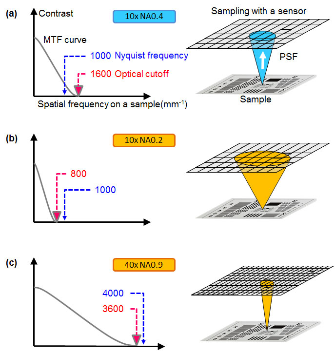
Figure 1 – MTF plot (left) and diagram in which a pixel array of an imager is projected onto a specimen (right) to explain the relation between PSF and the pixel pitch. (a) 10x NA 0.4, (b) 10x NA 0.2, (c) 40x NA 0.9

Sensitivity and noise: A high signal-to-noise ratio (SNR) is crucial for reliable data. In some cases, with very bright samples, this is easy to achieve. But in practice, the SNR has physical and technical limitations. The physical limitation is due to a statistical error in the number of photoelectrons generated in a sensor chip, which is determined by a sample’s brightness and the camera’s sensitivity. The camera’s sensitivity is dictated by its quantum efficiency (QE) and pixel area. Contrary to popular belief, QE is not the sole influencing factor for increased sensitivity. Pixel pitch can offer a greater degree of improvement, even with a minor increase. For example, if you change the pixel pitch of a sensor from 5.5 µm to 6.5 µm, the sensitivity improves by around 40%, whereas between a QE of 75% and 90%, there is only an improvement in sensitivity of 20%. QE should be carefully confirmed at your observation wavelength. Color cameras can have a QE of up to 60%, but it is worth noting that only a quarter to half of the pixels can detect fluorescent light at each wavelength, owing to the Bayer color filters usually applied to the sensors of color cameras.
The technical limitation is mainly caused by dark current and readout noise, including electrical noise on the electrical circuit. Today, sensor cooling is used to suppress hot pixels on CMOS and sCMOS sensors, though in the past this was traditionally used as a form of dark current suppression for long exposure times. However, the dark current is no longer an issue for most cameras at less than two-second exposure time. These limitations are expressed by Eq.2 and 3, which demonstrate that a camera’s sensitivity and the readout noise are key factors for a better SNR at short exposure times. For example, if you’re using a camera with 3 e-rms readout noise and 0.05 e-/s/pixel dark current, the contribution of the dark current to the background noise is about 2 decimal points smaller than the contribution of the readout noise at exposure times of less than 2 seconds.

Frame rate: Fast frame rates are the first requirement for smooth operation during live image viewing. Thanks to high-speed interfaces, such as USB 3.0, and CMOS technology, many recent cameras have frame rates that are higher than 30 frames per second (fps) with practical resolution. However, there are many applications that require even higher frame rates; for example, (1) pathology consultation and case conferences, which require smooth live imaging to follow the rapid microscope operation, (2) high-quality imaging of fast biological phenomena, (3) volumetric observation such as with light-sheet fluorescence microscopy (LSFM), and (4) computational imaging, including image-processing-based super resolution. In the case of dim fluorescence microscopy, there is a practical limitation related to exposure time. To resolve this issue, binning or other image processing techniques to enhance the SNR are used. The image distortion caused by the rolling shutter is a side effect of the fast readout feature of CMOS sensors. For fast moving samples, a global shutter followed by the global reset feature is an ideal solution that can help suppress the distortion.
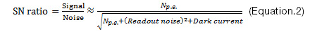
Dynamic range: In terms of monochrome cameras, dynamic range should be compared not as an analog-digital (AD) conversion bit depth, but as the ratio of full bit depth of image data to readout noise in bits. With proper high-end 16-bit cameras, issues with dynamic range during general fluorescence imaging are rare. The situation with color cameras is different. This is because color image data has an 8-bit limitation per each RGB channel with standard monitors. 8 bits is insufficient given that the human eye has greater dynamic range thanks to the ability to continuously adapt to brightness. The key to good image quality is a contrast curve designed to match the human eye’s response (Fig 2).
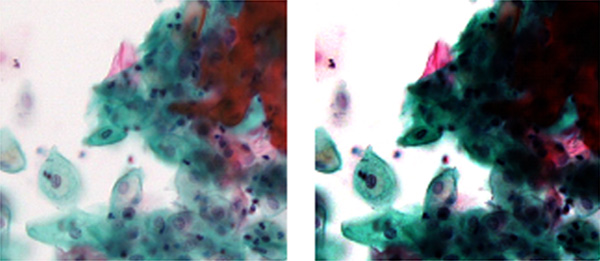
Figure 2 – An example of an image with a well-designed contrast curve (left) showing both pale bright cells and dark layered cells. The image with a poorly designed contrast curve (right) does not.
Field of view (FOV): There are some cameras with large image sensors that can provide a FOV over an 18 mm diagonal range, even with a 1X camera adaptor. Other cameras, those with comparatively smaller sensors, achieve a wide FOV by using camera adaptors with less than 1X magnification. However, doing so raises concerns about shading and optical aberration, particularly when you go farther from the optical axis (over 18 mm diagonally) (Fig 3) and when you perform image stitching (Fig 4).
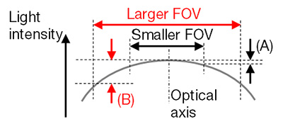
Figure 3 – Schematic figure of flatness of light intensity for FOV size. In general, a larger FOV provided by a lower magnification adaptor or a larger sensor produces worse flatness (B) than a smaller FOV configuration (A). The flatness strongly depends on the objective and optical configuration.
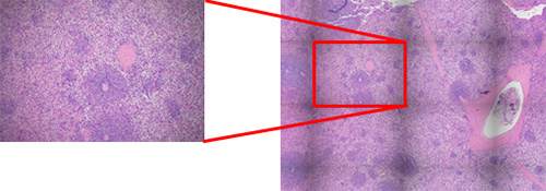
Figure 4 – The shading (nonuniformity of light intensity) stands out with image stitching (right); it is less obvious in the individual FOV image (left).
Color reproduction: Because human eyes have a different spectral response than camera sensors, camera vendors need to use multiple techniques to achieve colors on a monitor that are similar to the colors that you observe through microscope oculars. Proper white balance (WB) is the first step towards appropriate color reproduction. An automated WB feature dedicated to brightfield (BF) observation relieves you from time-consuming manual operation as it automatically detects the “white” background in a live BF image. To achieve high color fidelity, image processing typically involves a color matrix, which converts RGB signals from a sensor to R’G’B’ signals on a monitor. But this process is limited by the number of independent axes, which prevents, for example, adjusting eosin red independently from DAB-staining brown because both contain red signals. Multiaxis color adjustment is one way to bypass this limitation and to optimize the color for a variety of stains (Fig.5). Color space and color matching with a monitor are also important. Adobe RGB color space can express a larger range of color, which is especially beneficial for vivid greens such as Masson’s trichrome stain, but the image data for an Adobe RGB monitor cannot be displayed on other sRGB monitors without a proper ICC profile exchange.
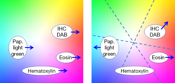
Figure 5 – With traditional color adjustment, (left) red enhancement for eosin affects all other stains, whereas multiaxis color adjustment (right) enables independent optimization of colors for each stain
All the key elements discussed in this section are not independent. Resolution, sensitivity, frame rate, and FOV, in particular, are deeply correlated. When observing an area of a sample, a smaller pixel pitch provides higher resolution, but less sensitivity, whereas a camera adaptor with lower magnification provides less resolution, higher sensitivity, and a wider FOV. To avoid phototoxicity damage to your sample during preparation, it can be helpful to use binning, which shortens the exposure time and increases the frame rate. Admittedly, some of the resolution is sacrificed when you use the binning technique, but the resolution is less crucial during the experiment set up phase.
Image Processing and Functional Imaging
For some applications, image processing is used to exceed the traditional optical and physical limitations. The extended focus image (EFI) technique can be used to acquire a thick sample in one image (Fig. 6), with stereo microscopes, in particular. High dynamic range (HDR) imaging is often used for industrial inspection because of its ability to capture reflective samples (Fig. 7). There are several techniques to enhance the SNR of fluorescence live images. For example, automatic multiframe averaging, which only functions when the microscope stage is stationary, is one way to achieve both a fast frame rate and high SNR, while minimizing phototoxic damage to your sample.
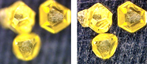
Figure 6 – EFI: (left) without EFI, (right) with EFI
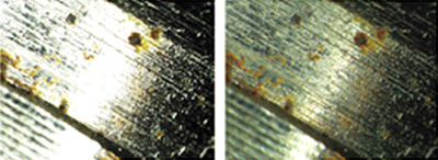
Figure 7 – HDR: (left) without HDR, (right) with HDR
Conclusion
Discussions regarding image quality are complex because the key elements are so interrelated; however, when selecting a microscope camera, it is best to base your decision on the most important requirements for your microscopic observation. There are a wide variety of camera choices on the market, enabling you to build a system that balances each element. A thorough evaluation before your purchase is a reliable method for determining the appropriate camera for your application because of the complexity and the performance differences between cameras that are not described in their specification sheets. Selecting the proper optics and camera for your application gives you more data and higher image quality, and advanced image processing enables you to go beyond the traditional limitations of microscopic imaging.
Author
Takeo Ogama
Scientific Solutions Division
OLYMPUS CORPORATION OF THE AMERICAS
Sorry, this page is not
available in your country.