Laser Cavity Resonance Modes and Gain Bandwidth
Laser Cavity Resonance Modes and Gain Bandwidth - Java Tutorial
In a typical laser, the number of cavity resonances that can fit within the gain bandwidth is often plotted as a function of laser output power versus wavelength. This interactive tutorial explores how varying the appropriate frequencies can alter curves describing the number of cavity modes and gain bandwidth of a laser.
The tutorial initializes with the gain bandwidth and cavity frequency set at values of 1.5 gigahertz and 476 terahertz, respectively. In order to operate the tutorial, use the mouse cursor to translate the Gain Bandwidth frequency slider between the ranges of 1 and 2 gigahertz. As this slider is translated, the yellow bandwidth curve changes shape to accommodate the new frequency range. The number of cavity modes can be adjusted with the Cavity Frequency slider, which simultaneously varies the modes drawn with red curves in the tutorial window.
A common misconception about lasers results from the idea that all of the emitted light is reflected back and forth within the cavity until a critical intensity is reached, whereupon some "escapes" through the output mirror as a beam. In reality, the output mirror always transmits a constant fraction of the light as the beam, reflecting the rest back into the cavity. This function is important in allowing the laser to reach an equilibrium state, with the power levels both inside and outside the laser becoming constant.
Due to the fact that the light oscillates back and forth in a laser cavity, the phenomenon of resonance becomes a factor in the amplification of laser intensity. Depending upon the wavelength of stimulated emission and cavity length, the waves reflected from the end mirrors will either interfere constructively and be strongly amplified, or interfere destructively and cancel laser activity. Because the waves within the cavity are all coherent and in phase, they will remain in phase when reflected from a cavity mirror. The waves will also be in phase upon reaching the opposite mirror, provided the cavity length equals an integral number of wavelengths. Thus, after making one complete oscillation in the cavity, light waves have traveled a path length equal to twice the cavity length. If that distance is an integral multiple of the wavelength, the waves will all add in amplitude by constructive interference. When the cavity is not an exact multiple of the lasing wavelength, destructive interference will occur, destroying laser action. The following equation defines the resonance condition that must be met for strong amplification to occur in the laser cavity :
N • λ = 2 • (Cavity Length)
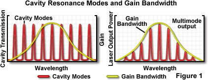
where N is an integer, and λ is the wavelength. The condition for resonance is not as critical as it might appear because actual laser transitions in the cavity are distributed over a range of wavelengths, termed the gain bandwidth. Wavelengths of light are extremely small compared to the length of a typical laser cavity, and in general, a complete roundtrip path through the cavity will be equivalent to several hundred thousand wavelengths of the light being amplified. Resonance is possible at each integral wavelength increment (for example 200,000, 200,001, 200,002, etc.), and because the corresponding wavelengths are very close, they fall within the gain bandwidth of the laser. Figure 1 illustrates a typical example in which several resonance values of N, referred to as longitudinal modes of the laser, fit within the gain bandwidth.
Laser beams have certain common characteristics, but also vary to a wide degree with respect to size, divergence, and light distribution across the beam diameter. These characteristics depend strongly upon the design of the laser cavity (resonator), and the optical system controlling the beam, both within the cavity and upon output. Although a laser may appear to produce a uniform bright spot of light when projected onto a surface, if the light intensity is measured at different points within a cross section of the beam, it will be found to vary in intensity. Resonator design also affects beam divergence, a measure of beam spreading as distance from the laser increases. The beam divergence angle is an important factor in calculating the beam diameter at a given distance.
对不起,此内容在您的国家不适用。


