To support equipment and instrument designers, we supply an extensive range of objectives and other optical parts to microscope-based imaging system manufacturers. These components help their engineers design high-quality optical inspection equipment easily and efficiently.
One essential component for these design projects is active autofocus technology. It provides automated focusing when combined with a microscope's motorized Z-mechanism, lighting system, objectives, and/or digital camera. These units bring many benefits to optical inspection system designs because they use an active method for bringing the sample into focus.
This post will explore the active autofocus method in depth—learn what it is, see how it compares to other methods, and discover its key advantages for optical inspection equipment designs, such as semiconductor inspection.
Comparing Microscope Autofocus Methods: Active vs. Passive
In general, there are two types of autofocus systems:
- Active systems irradiate light from a dedicated autofocus light source onto the specimen and focus based on the returned light. This technique is for advanced inspection systems where the sample lacks contrast, such as flat panel and bare wafer inspection systems. There are different types of active autofocus technology. A pupil-splitting system allows detection of the focus direction without moving the specimen above or below the initial plane of focus, making the focus fast and easy to track. With single-point autofocus systems, the focus point is at the center of the field of view on the sample surface.
- Passive systems focus using the observed image. This technique (Figure 1) is often referred to as the image contrast method. In the passive method, it is difficult to determine the focusing direction, so the Z-stage must be moved up and down to detect the increase or decrease in contrast of the sample. This slows down the focus speed and makes it difficult to keep track of the focus. However, this method has the advantage of being relatively inexpensive.
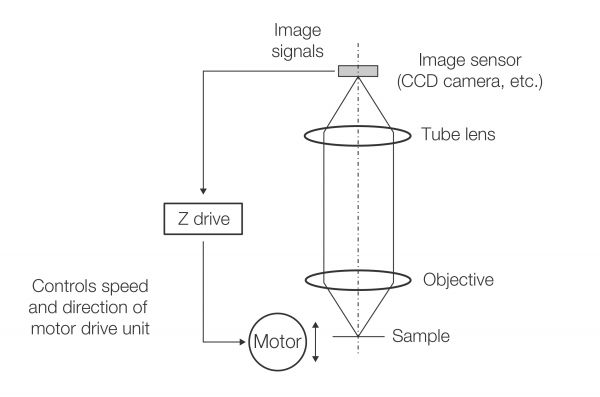
Figure 1. Schematic diagram of the passive autofocus method
Developing an Active Autofocus with a Multi-Point System
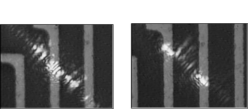
Complicated or miniaturized semiconductor designs have led to new autofocus challenges during microscopic inspection. Wiring patterns are finer, and step structures are more complicated.
These autofocus challenges (Figure 2) include:
- Unstable movement of the focus position between the top and bottom of the step when the sample shifts slightly sideways
- Deterioration of the signal-to-noise ratio (SNR) of the focus error signal due to scattering of the autofocusing light at the step edge
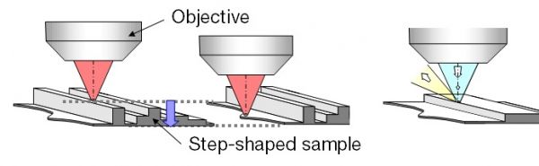
Figure 2. Causes of unstable focus in semiconductor samples: (left) changes in focus position and (right) scattering at step edges.
To solve these problems, we developed an active autofocus system that uses multiple focus detection points (Figure 3, right). We have also added a function to offset the focus position to the desired observation position by shifting the optical axis of the autofocusing optical system's relay lens. This has eliminated the unstable focus issue (Figures 4 and 5).
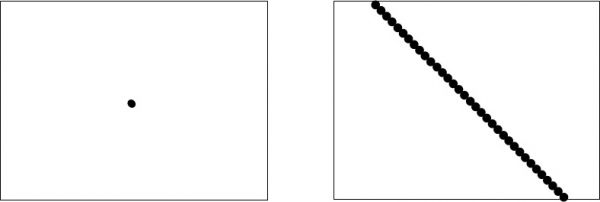
Figure 3. Comparison of in-focus detection points on the sample surface: (left) single-point autofocus system, (right) multi-point autofocus system.
This autofocus technology can be supplied as a component for integration into larger optical inspection equipment. Its main use case is semiconductor inspection equipment.
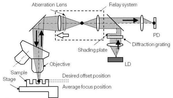
Figure 4. Focusing position offset function.
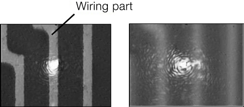
(a) In the single-point system, shifting the sample to the side will shift the focus position. |
(b) In the multi-point system, shifting the same sample to the side does not change the focus position. |
Figure 5. Comparison of focus stability against lateral misalignment of a step-shaped sample (bright spots indicate in-focus detection points). | |
If you’d like to learn more about our active autofocus products or our high-quality optical components to incorporate into your microscope design, please contact us at www.olympus-lifescience.com/oem-components.
Related Content
OEM Microscope Components for Integration
How to Minimize an Optical System for a Compact Imaging Device