In brightfield reflected light microscopy, proper use of the two variable diaphragms illustrated in Figure 1, the aperture iris diaphragm (closer to the light source) and the field iris diaphragm (closer to the specimen), enable the use of the highly desirable Köhler illumination.
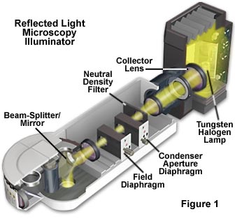
These diaphragms are in the opposite of their respective positions in transmitted light, the aperture diaphragm now being closer to the light source. Such illumination provides bright light evenly dispersed across the plane of the field of view of the focused specimen. Köhler illumination provides glare-free light utilizing the maximum share of the objective's numerical aperture consistent with good contrast and resolution.
It is important to note, that in these reflected light systems, the objective serves a dual function: on the way down as a matching well-corrected condenser properly aligned; on the way up as an image-forming objective in the customary role of an objective projecting the image-carrying rays toward the eyepiece. In a transmitted light system, changing the objective requires an adjustment in the numerical aperture of the condenser to match that of the new objective. However, in reflected light, the objective and condenser numerical apertures change simultaneously with a new objective. Conjugate planes are similar to those described for transmitted light, with images of the light source being formed in the back focal plane of the objective and within the aperture diaphragm iris opening. This serves to reduce the complexity of establishing the conditions of Köhler illumination in reflected light microscopy.
Reflected Light Illuminators
Explore how voltage is adjusted to control the illumination intensity of a tungsten-halogen lamp in a reflected light illuminator.
Start Tutorial »A function of Köhler illumination (aside from providing evenly dispersed illumination) is to ensure that the objective will be able to deliver excellent resolution and good contrast even if the source of light is a coil filament lamp. The aperture iris diaphragm controls the angle of light striking the specimen from every azimuth in a full cone in brightfield reflected light. The objective's numerical aperture determines the angle of light which can be "captured" as it is reflected from the specimen. Other factors being equal, the higher the numerical aperture, the better the resolution of the objective, i.e. the better the objective is able to clearly separate small details lying close together. The system's vertical illuminator contains the aperture iris diaphragm so that the back of the objective itself does not have to be occluded.
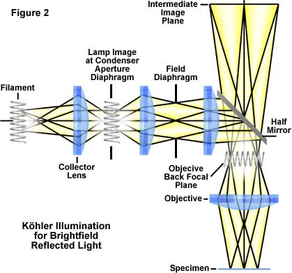
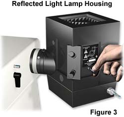
In Köhler illumination, the system is arranged (Figure 2) so that the image of the coil filament of the lamp is brought into focus at the plane of the aperture iris diaphragm; it is also in focus at the back focal plane of the objective. Assuming there is no frosted filter in the light path of the illuminator, when an eyepiece is removed, the image of the lamp filament can be seen at the back of the objective. In most systems, the lamp housing exterior has a set of centering screws (Figure 3), which enable you to center the lamp filament by moving the filament in a north-south or east-west direction. Also, the closing or opening of the aperture iris diaphragm is observable at the back focal plane of the objective, as described above.
The field iris diaphragm is conjugate (pre-focused) with the focused specimen, the intermediate image plane at the plane of the fixed diaphragm of the eyepiece, and the retina of the eye.
Reflected light microscopy is of growing interest, especially in regard to its increasing usefulness in fluorescence microscopy. The rapidly growing semiconductor industry has also led to an increase in the use of reflected light microscopes, which continue to be very useful in classical applications such as metallography, ore petrography, and materials research.
In practice, the specimen is first focused with a medium magnification objective, usually the 10x, and the aperture of the pre-focused field diaphragm is closed until it is visible in the periphery of the viewfield. If the field iris diaphragm is not centered, the centering screws on the vertical illuminator are used to move a partially closed iris opening into the center of the field. The diaphragm is then opened until it just disappears from view or from the area delineated by the film frame in a photomicrography reticle. Next, the lamp filament is centered and focused (if this has not been done at the factory), and the aperture diaphragm is set for the optimum specimen contrast and image quality. These steps are discussed in detail in the sections below.
Adjustment of the Reflected Light Microscope
for Köhler Illumination
Eyepieces and Field Diaphragm
- Choose a sample that has a high degree of reflectivity to maximize the amount of light reflected back into the objective during the initial Köhler illumination configuration steps. An ideal choice is an integrated circuit on highly reflective silicon, a section of highly polished metal, or a smooth metallic thin film. The specimen should possess some degree of detail or texture that can be used to find the focal plane of the specimen.
- Place the reflective specimen on the stage and activate the light source, which is usually a tungsten-halogen bulb positioned in a lamp housing similar to the one illustrated in Figure 3. Rotate the nosepiece to position a medium power objective, such as the 10x, facing the specimen. If the bulb is working properly, a small circle of light about 3 millimeters in diameter should be projected by the objective onto the surface of the specimen.
- While watching the objective and the specimen, use the coarse focus knob to raise the stage until it is a couple of millimeters below the front lens of the objective. Be very careful not to drive the specimen into the objective front lens. Next, while observing the specimen through the eyepieces, slowly lower the stage with (at first) the coarse and then the fine focus knob until specimen details come into sharp focus. If the focus point is missed, start over again with slightly less distance between the objective front lens and the specimen. In many instances it is easier to find the correct focus if the specimen is moving while trying to establish focus. Do this by either rotating a circular 360-degree stage or using the mechanical stage knobs to translate the specimen back and forth in the viewfield.
- Adjust the interpupillary distance on binocular microscopes once the specimen is in sharp focus. Diopter adjustments on each of the eyepieces should also be made at this time.
- Many polarizing and differential interference contrast (DIC) microscopes are equipped with circular graduated stages that rotate a full 360 degrees around the optical axis of the microscope. These microscopes are usually equipped with individual adjustments (through set screws in the nosepiece) for each objective to allow the optical axis of the objective to be made concentric with the optical axis of the microscope. It is a good idea to made this adjustment before proceeding.
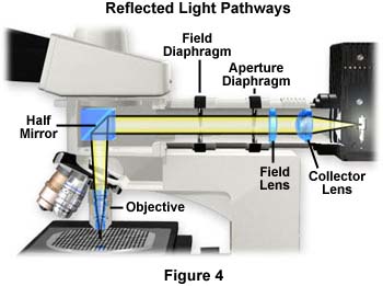
- The next step is to adjust the field diaphragm, which is the iris diaphragm closest to the front of the microscope as illustrated in Figure 4. Sometimes the diaphragm is labeled "F" or "Field" directly on the illuminator housing. Use the lever adjustment to close the field iris diaphragm until you begin to see the leaves in the viewfield. Continue to close the diaphragm to the point where the lever stops and only a small opening is visible in the eyepieces. The specimen and the leaves of the diaphragm should both be in sharp focus, a setting that is usually made at the factory because most modern reflected light microscopes are not equipped to allow adjustment of the axial position of the field diaphragm (it cannot be focused). This is because the objective serves a dual role of also being the condenser, so critical focal planes are preset at the factory to minimize microscope alignment errors. In most instances, there will be slight differences between the focus and center of the field diaphragm in the various objectives, but this small fluctuation can usually be neglected.
- A set of centering knobs is positioned on the outer housing of the vertical illuminator near the field diaphragm that allow the user to center the field diaphragm in the viewfield. Use these knobs to center the field diaphragm image, then slowly open the iris leaves until the diaphragm image is just outside the field of view. If photomicrography is the prime consideration, the field diaphragm should be opened only wide enough to allow the area outlined in the film frame (inscribed into a photomicrography reticle) to be visible. Changing objectives will not require adjustment of the field diaphragm size setting, because the new objective will also act as the condenser and the relationship will remain the same. This is easily verified by closing the field diaphragm to a pre-determined size in relation to the photomicrography or measuring reticle. After changing the objective, the size of the image in the viewfield will change but the size relationship between the field diaphragm and the reticle will not.
Filament Alignment and Aperture Adjustment
- Just as with Köhler illumination in transmitted light, adjustment of the ("condenser") aperture diaphragm in reflected light is critical in controlling specimen contrast, reducing diffraction and glare artifacts, and producing the finest image quality. The image of the filament should be in focus and completely fill the aperture diaphragm, similar to the situation with transmitted light.
- The first step is to center and focus the lamp filament. Some modern reflected light microscopes (especially high-end research models) are equipped with a pre-centered tungsten-halogen lamp in a housing that is also fitted with a collector lens and a diffuser screen. There are no adjustments to these systems, but many older epi-illumination systems have lamps that must centered, and adjustment mechanisms are provided for this purpose. The first step is to remove (if possible) the glass diffusion filter that spreads illumination evenly over the view field. Next, use the adjustment knobs (see Figure 3) to center the filament while observing the conjugate image in the objective back focal plane. This is done in a manner similar to that for transmitted light microscopes, where the eyepiece is removed and the condenser aperture and filament image are viewed at the back focal plane of the objective through the eye tube. Visitors and students are invited to explore filament alignment in the following interactive Java tutorial:
Lamp Filament Alignment
Practice aligning and focusing the lamp filament and then observing its image at the back focal plane of the objective.
- When the eyepiece is removed from the eye tube, an image of the lamp filament (in sharp focus) should be visible at the back focal plane of the objective, along with a partially closed aperture diaphragm. This observation is facilitated by using a phase telescope, a Bertrand lens (an accessory usually found on polarized light microscopes) or through an end cap with a pin hole in the center. The latter can be made from an eyepiece plug that is used to protect the microscope's interior during shipment. If the ground glass diffuser screen has not been (or can't be) removed, an evenly illuminated light disk should appear in place of the filament coils. If the filament is not centered, "hot spots" will appear in the light disk, which can be remedied by adjusting the screws on the lamphouse (Figure 3). Keep making incremental adjustments until illumination is uniform over the entire light disk.
- The last step is to adjust the opening of the aperture diaphragm, which is usually identified by the letter "A" or the word "Aperture" on the vertical illuminator's exterior. In a transmitted light microscope, the condenser aperture diaphragm must be readjusted each time a new objective of differing numerical aperture is inserted into the light path. This is due to the fact that the objective and condenser are separate entities and changing the objective numerical aperture does not affect the condenser. To compensate, the condenser aperture diaphragm must be opened or closed to provide an illuminating cone of light that matches the numerical aperture of the objective. However, in reflected light microscopy the objective also acts as the condenser (as discussed above, providing both illuminating and image-forming light pathways), and the numerical apertures change accordingly when a new objective is selected.
Condenser Aperture Diaphragm Adjustment
Discover how image contrast is maximized and how diffraction artifacts can occur during adjustment of the condenser aperture diaphragm.
Start Tutorial »- Determining the correct setting of the aperture diaphragm is paramount in obtaining images that are free of diffraction artifacts, possess sufficient contrast, and are of the highest quality. Often, this results from a trade-off where a compromise is reached between maximizing image contrast without introducing erroneous artifacts due to refraction and diffraction. As mentioned above, the aperture diaphragm must be reset with each objective change in transmitted light microscopy. However, in reflected light microscopy, the objective and "condenser" change with simultaneous increments in numerical aperture and a single setting can be chosen for the aperture diaphragm. This setting is typically between 60 and 95 percent open, but will vary from specimen to specimen and will depend heavily upon the reflectivity of the specimen. Highly reflective specimens will require a smaller aperture to reduce glare and enhance contrast, but this is best undertaken on a case-by-case basis. The best procedure is to first open the aperture to its widest setting, then slowly close it while viewing the specimen to optimize contrast. In photomicrography, it is often wise to "bracket" a set of micrographs, each with a slightly different aperture size.
The techniques outlined above for brightfield reflected light microscopy also apply to microscopes equipped for crossed polarization, fluorescence, and differential interference contrast (DIC). In fact, the microscope can be adjusted for Köhler illumination while in any of these modes, and often contrast enhancements can be interchanged without the necessity of realigning the microscope illumination.