Interference Filters
Interference Filters - Java Tutorial
Recent technological achievements in bandpass filter design have led to the relatively inexpensive construction of thin-film interference filters featuring major improvements in wavelength selection and transmission performance. These filters operate by transmitting a selected wavelength region with high efficiency while rejecting, through reflection and destructive interference, all other wavelengths. Explore how interference filters operate by selectively transmitting constructively reinforced wavelengths while simultaneously eliminating unwanted light with this interactive tutorial.
The tutorial initializes with a single ray of white light (simulated by a yellow sine wave) incident on the surface of an interference filter at a 20-degree angle. As the light passes through the filter, red wavelengths (represented by red sine waves having a peak of 713 nanometers) are reinforced by constructive interference and passed through, but other wavelengths are reflected away (symbolized by the blue wavelengths) and diminished in intensity through destructive interference inside the filter. In order to operate the tutorial, use the Incident Angle slider to vary the angle of incidence of white light through a range of zero to 20 degrees. As the slider is translated to the left, the peak wavelength passed through the interference filter decreases from 713 nanometers (at a 20-degree incident angle) to 626 nanometers (incident light normal to the filter surface), and the amount of reflected light is also decreased proportionally.
Modern interference filters are modeled after the Fabry-Perot interferometer, designed in the late 1800s by Charles Fabry and Alfred Perot, and are constructed with several layers of thin films applied to an optically flat transparent glass surface. The original interferometer consisted of a device having two partially transparent mirrors separated by a small air gap whose size could be varied by translating one or both of the mirrors. Today, more sophisticated interferometers utilize a variety of mechanisms to measure the interference between light beams, and are often employed to monitor thin-film thickness during fabrication of interference filters and mirrors.
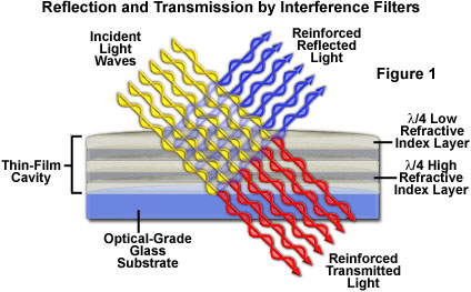
Interference filters can be produced with very sharp transmission slopes, which result in steep cut-on and cut-off transition boundaries that greatly exceed those exhibited by standard absorption filters. To produce modern interference filters, successive layers of dielectric materials, with thickness values ranging between one-quarter and one-half of the target wavelength, are deposited onto an optically flat glass or polymer surface in a vacuum. Light that is incident on the multi-layer dielectric surface is either transmitted through the filter with constructive reinforcement, or reflected and reduced in magnitude by destructive interference (see Figure 1). The filter bandpass, which is determined by the nature of the layered dielectric surface, determines the wavelengths of light that are allowed to be transmitted and multiply reflected when passing through the filter. Blocked wavelengths that not reinforced and passed by the filter are reflected away and removed from the optical path.
The dielectric materials utilized to fabricate interference filters are generally nonconductive materials having a specific refractive index. Traditional bandpass interference filters are manufactured using zinc sulfide, zinc selenide, or sodium aluminum fluoride (also termed cryolite), but these coatings are hygroscopic and must be insulated from the environment by a protective coating. In addition, the zinc and cryolite salts suffer from low filter transmission characteristics and temperature instability, which further reduces their performance, even though they are simple and relatively cheap to manufacture. After deposition of the thin film salt layers, a final layer of glass or an abrasion-resistant protective coating of silicon monoxide is added.
Introducing semi-transparent layers of metal oxides (known as hard coatings) into thin-film coating technology has alleviated many of the environmental problems associated with interference filters, and dramatically improved their temperature stability. The thin coatings of metals and salts, each with a unique refractive index, are applied in successive layers having alternating high and low refractive index values. The critical element of this design is the interface between two dielectric materials of differing refractive index (one much higher than the other), which is responsible for partially reflecting incident light forward and backward through the filter and producing the interference effect that results in wavelength selection. Reinforced and transmitted wavelength values are determined by the thickness and refractive index of the interspersed dielectric layers. Even though the thin coatings themselves are transparent, light waves reflected and transmitted by the dielectric materials interfere to produce brilliant colors that appear to be emanating from the filter surface.
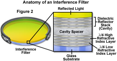
Dielectric coatings are often bundled into units termed cavities, which are constructed of three to five alternating salt and metal oxide (and sometimes pure metal) layers separated by a wider layer of magnesium fluoride termed a spacer (see Figure 2). The spacers are produced with a thickness that corresponds to even multiples of a quarter or half wavelength in order to reflect or transmit light in registration with the dielectric layers. Increasing the number of cavities utilized to build an interference filter produces a proportional increase in the slope of the cut-on and cut-off wavelength transmission boundaries. Filters featuring up to 15 stacked cavities can have a total of over 75 individual dielectric layers and display bandwidths only a few nanometers in size.
Virtually any type of filter can be designed and constructed with thin-film interference coating technology, including bandpass, shortpass, longpass, dichroic beamsplitters, neutral density, and a variety of mirrors. As discussed above, the number of layers and cavities is utilized to control, with very high precision, the nominal wavelength, bandwidth, and blocking level of the filter. Filters with multiple transmission bands, such as the complex triple-band filters so popular for fluorescence microscopy, can be fabricated with this technique.
The high degree of blocking obtained with thin-film interference filters only applies to a finite wavelength range, beyond which effective blocking drops off dramatically. The range can be extended by adding auxiliary components, such as wideband blockers, but often at a compromise in peak transmission values. In addition, the coating materials utilized in thin-film production are limited in their range of transparency. Once the range has been exceeded, these coatings can become highly absorbing rather than highly reflecting or transmitting, thus reducing the efficiency of the filter. Coating absorption characteristics can also be wavelength-dependent, so the same coating utilized for longpass filters will usually not perform adequately at lower wavelengths in the violet and ultraviolet region. Finally, interference thin-film coatings are sensitive to the incident angle of illumination. As this angle is increased, the spectral characteristics of the coating tend to shift towards shorter wavelengths (the spectrum is blue-shifted). Another drawback is that interference coatings often produce polarized light at high incident angles, an effect that is not always desirable. Regardless of the deficiencies found in thin-film coatings, this technology is still one of the most suitable for wavelength selection in a wide variety of applications.
Sorry, this page is not
available in your country.