How Olympus Super Resolution and Spinning Disk Technology Achieves Fast, Deep, and Reliable Live Cell Super Resolution Imaging
Introduction
In the decades following the discovery of fluorescent proteins, live cell imaging has become an indispensable tool for the investigation of intracellular functions inside tissues and cells in the field of life science research. Today, various super resolution microscopy techniques are advancing fluorescence imaging even further. Super resolution imaging is attracting attention as a revolutionary tool in the life science field because it enables the observation of fine structures that are less than 200 nm (nm=10-9 m) in size, an imaging performance that is unattainable using a conventional optical microscope. However, applying super resolution microscopy techniques to live cell imaging is limited because of time resolution and phototoxicity issues. In addition, the reliability (quantitative performance) of imaging data is also a significant concern because image processing including estimation or spatial frequency shift can form artifacts that corrupt results.1
In response, Olympus has developed the super resolution IXplore SpinSR system for live cell super resolution imaging. This system utilizes super resolution components as well as the optical sectioning capability of confocal fluorescence microscopes. The IXplore SpinSR system simultaneously achieves high reliability, fast image acquisition, low phototoxicity, and deep tissue observation, which cannot be done using conventional methods. Data reliability is ensured owing to our Olympus Super Resolution (OSR) technology. Based on optical theory, our OSR processing algorithms are capable of obtaining a spatial resolution of 120 nm, providing highly reliable results below the diffraction limit. Fast image acquisition is achieved using the spinning disk confocal microscope technique. Using super resolution SoRa disk technology2, phototoxicity is also reduced to 30% of conventional techniques. Deep tissue observation is achieved using silicone immersion objectives3 and through the optical sectioning capability of confocal microscopes.
In this paper, we will explain the principles behind Olympus Super Resolution (OSR) technology and the optical design of the IXplore SpinSR system.
What Is Super Resolution?
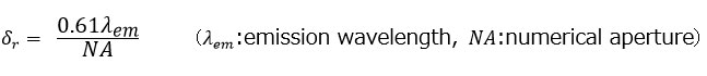
The spatial resolution of a fluorescence microscope (δr ) is defined as the minimum resolvable distance between two small points. According to the Rayleigh criterion, this resolution is expressed by Equation 1.
Equation 1
The resolution δr is obtained from an intensity distribution formed by a single fluorescent point on the imaging plane. This intensity distribution is known as the point spread function (PSF). As shown in figure 1, if the distance between two points is less than Rayleigh criterion δr , two points cannot be separately identified. When the distance is at the Rayleigh criterion, the intensity between two points is reduced by 26% at most.
The spread of the PSF depends on the cutoff frequency, and they are closely tied to each other. An increase of the cutoff frequency results in a decrease of the value of spatial resolution. The cutoff frequency of fluorescence microscopes ƒc_wf is shown in Equation 2.

Equation 2
Spatial frequency information of emission intensity distribution is limited by the cutoff frequency ƒc_wf and transferred to the imaging plane. Therefore, the inverse of the cutoff frequency ƒc_wf is a theoretical limit of the size of the observable structure. Microscope techniques that go beyond the resolution determined by the cutoff frequency ƒc_wf in Equation 2 are categorized as super resolution microscopy.
In a confocal fluorescence microscope, the theoretical cutoff frequency is twice than that of a widefield microscope ƒc_wf, resulting in two-times super resolution as a theoretical resolution limit. However, the actual resolution is generally the same as that of a widefield fluorescence microscope because high-frequency signals are weak. While resolution is improved with narrowed pinholes, signal intensity near the cutoff frequency is still low. Therefore, a confocal fluorescence microscope cannot be used as a super resolution microscope.
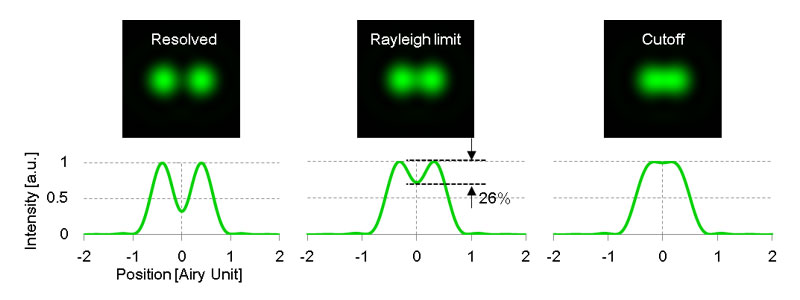
Figure1.Scheme of two-point resolution.
Spinning Disk Confocal Fluorescence Microscopy
The IXplore SpinSR system realizes two-fold resolution over widefield fluorescence microscopy by making the best possible use of information around the cutoff frequency of confocaⅼ fluorescence. It also realizes high speed imaging as fast as 200 fps by utilizing spinning disk confocaⅼ fluorescence microscopy.
In confocal fluorescence microscopy, emission fluorescence produced by illuminating samples with excitation light spots passes through pinholes before it reaches the detector. Spatial distribution of detected fluorescence signal is imaged while scanning the excitation light spots via two-dimensional scanning. Confocaⅼ fluorescence microscopy is widely used as a tool to obtain three-dimensional spatial distribution of fluorescence signal because of the optical sectioning capability in the z-dimension.
A spinning disk confocal microscope simultaneously illuminates many excitation light spots and detects the produced fluorescence from each spot in parallel. A rotating confocal disk scans excitation spots while corresponding pinholes on the intermediate imaging plane reduce the out of focus fluorescence. The spatial distribution of the fluorescence signal is then detected by a camera (Figure 2). As shown in the scheme of pinhole array in Figure 2, the distance between pinholes on the confocal disk are large enough to prevent signal crosstalk between pinholes.
The IXplore SpinSR system’s detection sensitivity is improved through scientific complementary metal–oxide–semiconductor (sCMOS) technology. An sCMOS camera has higher quantum efficiency than that of a photoelectric multiplier tube which is widely used in confocal microscopes; therefore, the IXplore SpinSR system’s sCMOS image sensor acquires images with a higher signal-to-noise ratio (SNR) than would be possible with a photomultiplier tube. Using the super resolution SoRa disk, detection loss by confocal pinholes is significantly reduced, and fluorescence is detected at three-times the brightness compared with conventional methods, resulting in low phototoxicity. (See appendix.)
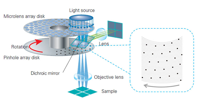
Figure 2. Schemes of the optical system of a spinning disk confocal microscope. The confocal disk is set on the intermediate imaging plane. The disk rotates on its center axis while excitation light is irradiated on the blue circular portion. Right scheme shows pinhole array for sample illumination. The pinholes are far enough apart for simultaneous scanning of many excitation spots without interference.
Olympus Super Resolution (OSR) Theory
The IXplore SpinSR system improves the detection efficiency of the spatial frequency up to twice the cutoff frequency of widefield fluorescence microscopes, by optimizing the pinhole size.4 The super resolution image is obtained through OSR processing on the acquired image. OSR is a filtering process that amplifies or attenuates a specific spatial frequency component in the image. Reliable imaging with fewer artifacts can be obtained with the optimized amplification factor without spatial frequency shift in the acquired image. The Wiener filter is sometimes used for deconvolution in image processing. However, the Wiener filter sometimes forms artifacts, decreasing the reliability of image data.
OSR processing uses a spatial frequency filter which amplifies high-frequency components with apodization which gradually attenuates near the confocal fluorescence microscope cutoff frequency (referred to as OSR filter). This results in improved resolution with fewer artifacts. Figure 3a compares the amplification factor at each spatial frequency of both the OSR and the Wiener filters. It confirms that the OSR filter does not over-amplify the medium frequency component, and adequately amplifies the components near the cutoff frequency.
In Figure 3b and 3c, PSFs and optical transfer functions (OTFs) are compared between before and after applying the OSR filter to a confocal fluorescence microscope image with a pinhole size corresponding to the Rayleigh criterion. It confirms that two-times higher resolution than that of widefield fluorescence microscopes is achieved by OSR processing.
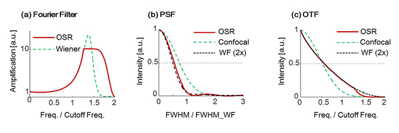
WF(2X): Virtual curve with 2x cut off frequency
Figure 3. Characteristics of OSR filter and a Wiener filter and their effects. (a) Shapes of the filters. (b) PSF. (c) OTF.
Imaging simulation results after applying the OSR and the Wiener filters are compared in Figure 4. By comparing the images after applying the OSR filter (Figure 4c) to applying the Wiener filter (Figure 4d), it can be seen that there are fewer artifacts near the object in the images after applying the OSR filter than when using the Wiener filter. IXplore SpinSR images of a biological sample, stained actin filaments in a fixed cell, are shown in Figure 5. The excitation wavelength was 488 nm, and the Olympus UPLSAPO100XS objective was used. Images acquired by the IXplore SpinSR system before applying the OSR filter, after applying the OSR filter, and applying the Wiener filter instead of the OSR filter are shown in Figures 5a, 5b, and 5c respectively. The OSR filter improves the image resolution as much as the Wiener filter while reducing artifacts and maintaining a higher SNR. Therefore, OSR processing can be useful for live imaging and quantitative analysis of biological samples.
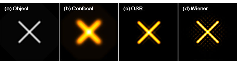
Figure 4. Simulated results of imaging resolution. (a) Object. (b) Image by confocal fluorescence microscope. (c) Image with the OSR filter. (d) Image with a Wiener filter.
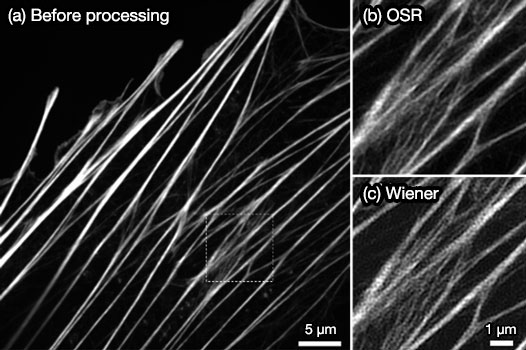
Figure 5. Fluorescence images of stained actin filaments in a fixed cell. (a) Confocal fluorescence image acquired by the IXplore SpinSR system. (b,c) Magnified image of the highlighted portion (a) with the OSR filter (b), with a Wiener filter (c).
As other examples, images of fluorescent beads (Φ100 nm)and stained nuclear pores are shown in Figures 6 and 7. They also indicate that the OSR filter can achieve high reliability and a high SNR, which suggests that the IXplore SpinSR system’s super resolution technique is suitable for live cell imaging.5
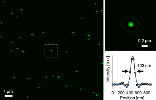
Figure 6. Super resolution image of fluorescent beads (Φ100 nm) acquired by the IXplore SpinSR system and a corresponding intensity profile.
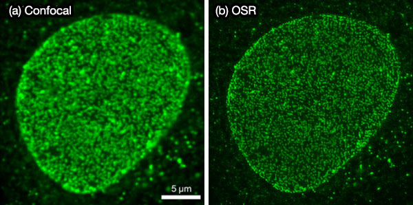
Figure 7. Fluorescence images of stained nuclear pores in a fixed cell. Confocal image (a) and OSR image (b) by the IXplore SpinSR system.
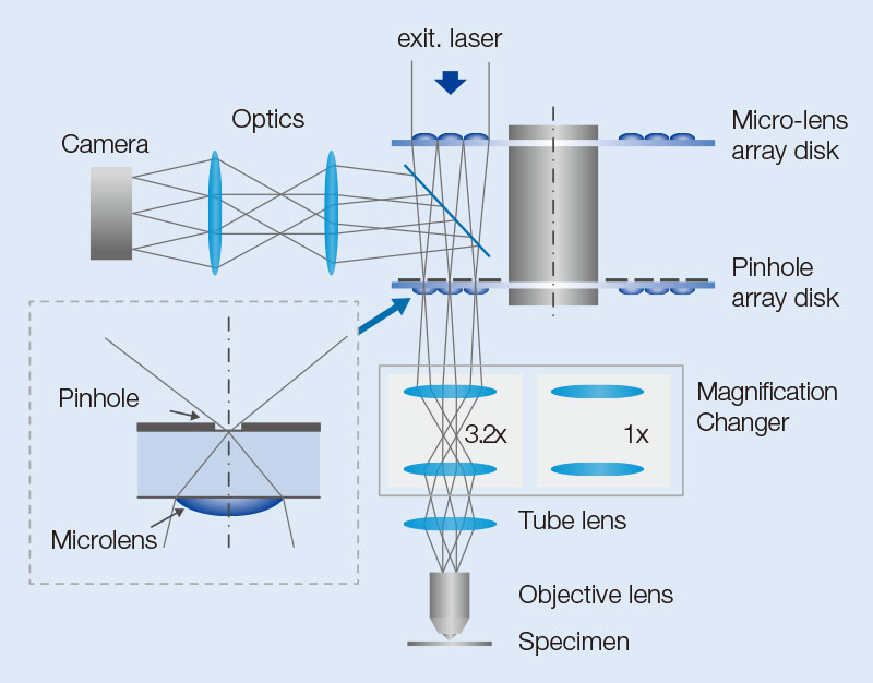
Optical System
The IXplore SpinSR system is composed of an objective, imaging lens, optical system for magnification, confocal spinning disk, and an sCMOS camera (Figure 8). Excitation laser light introduced into the confocal spinning disk forms many excitation light spots by an array of microlenses. The light then passes through a dichroic mirror and pinholes arranged to match each focal point of the microlens array. After passing through the pinholes, the beam size is optically adjusted to the pupil diameter of the objective and then passes through a 1/4 wavelength plate (λ/4 plate). Parallel light, after passing through the imaging lens, is transformed into many excitation spots and illuminates the sample through the objective, resulting in the induction of fluorescence. Fluorescence light is detected by the same objective but moves in the opposite direction of the excitation light. Then, fluorescent spots are formed by passing through the optical system for magnification and the corresponding pinholes. The fluorescence spots, reflected by the dichroic mirror, form an image on the camera.
The optical system for magnification is used for switching between confocal observation and super resolution observation. In super resolution mode, the size of fluorescent spots projected on the pinholes during fluorescence detection is optimized (Figure 8a), and the excitation beam is expanded to fill the objective’s pupil (Figure 8b). In confocal observation, the intermediate imaging plane is projected on the sample surface at unit magnification, allowing confocal imaging with a wide field of view corresponding to a field number (FN) of 18.8.
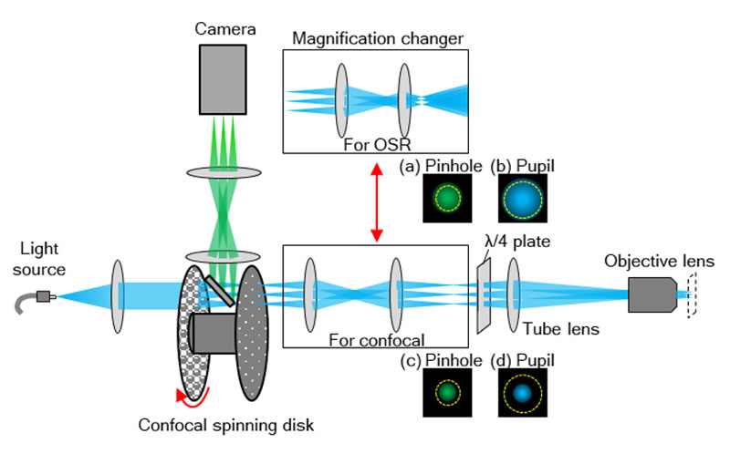
Figure 8. Structure of equipment’s components. Optical system for magnification is switched depending on the purpose. For observation using OSR, the magnification system that optimizes pinhole size and occupies the full pupil of the objective is used. For confocal observation, the magnification system that enables observation across a wider field of view is used.
IXplore SpinSR with the optical system for magnification enables high field flatness. It is designed for minimizing aberration by connecting the microscope’s optical system and the confocal spinning disk unit. Stitched images of 16 adjacent fluorescence images (4 vertical × 4 horizontal) are shown in Figure 9. Figures 9b and 9a are images obtained by system designed for IXplore SpinSR and general system, respectively. In the image obtained by the general system, grid-like intensity distribution are observed near the junctions of the small fluorescence images, accompanied by decreased intensity. In contrast, the system designed for IXplore SpinSR provides high flatness without artifacts, indicating that the magnification optical system is optimized for the optical performance of the IXplore SpinSR system up to the peripheral part of the field.
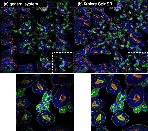
Figure 9. Images in which 16 (4 vertical × 4 horizontals) neighboring fluorescence images are stitched together. Each fluorescence image is acquired by system designed for IXplore SpinSR (b) and general system (a).
The λ/4 plate transforms linear polarization of excitation laser light to circular polarization to obtain an equivalent resolution in both the X and Y directions. Otherwise linearly polarized light forms diffraction limited spots with a different full-width half-maximum value in the X and Y directions, resulting in the formation of oval-shaped excitation light spots (insets in Figure 10). Using the UPLSAPO100XS objective, more than 20% difference between X and Y directions would be observed as shown in Figure 10. Transformation of linearly polarized light to circularly polarized light by the integrated λ/4 plate enables observation of fine structures without distortion. As for the detection side, randomly polarized fluorescence light emitted from samples is not effected by the λ/4 plate.
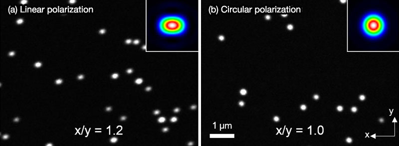
Figure 10. Fluorescence images of fluorescent beads (Φ 100 nm) with linear polarization (a) and with circular polarization (b). Insets are simulated excitation spots.
Conclusion
Our Olympus Super Resolution (OSR) technology and optimized optical design enable us to achieve a spatial resolution of 120 nm. This is an improvement over the conventional widefield microscope, which was limited to a spatial resolution of 200 nm. Image processing without spatial frequency shift nor estimation of object shape provides highly reliable results. We believe that this technology is useful for investigating molecular dynamics, which is a potential application that had not been clarified until now.
Appendix
Each confocal pinhole on the disk has a microlens that enables you to image with lower laser power, reducing photobleaching and phototoxicity in your sample while enabling bright super resolution images2. In regular confocal microscopes, image formation is a product of the illumination point spread function (PSF) and detection PSF. Looking at the image formation on the pinhole at position D from the optical axis, it’s the product of the illumination PSF and detection PSF, and we can see that information from position D/2 from the optical axis is transmitted but not resolved. To correct this, a microlens is fitted in the pinhole, and the individual focal points projected onto the pinhole are optically reassigned to the center, creating an ideal image and increasing the brightness and resolution6-8. This process makes the resolution nearly equal to that of an ideal confocal microscope in which the pinhole has been reduced to an infinitesimal size.
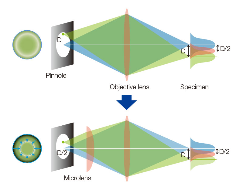
Appended figure 1. Principle and cofiguration of SpinSR with SoRa disk
Author
Dr. Yasuo Yonemaru
Optical System Development
Research and Development
Olympus Corporation
References
- J. Lopez, et al. “A deconvolution revolution for confocal image enhancement”, BioOptics World, 55, Issue 01, pp. 85–88, January 2019.
- T. Azuma and T. Kei, "Super-resolution spinning-disk confocal microscopy using optical photon reassignment", Opt. Express, 23 (11), pp. 15003–15011, 2015.
- (White Paper) A. Samuelsson, “Silicone Immersion Objectives Answer the Call for Higher Resolution”, (https://www.olympus-lifescience.com/resources/white-papers/silicone_immersion_objectives_for_higher_resolution/)
- S. Hayashi, "Resolution doubling using confocal microscopy via analogy with structured illumination microscopy", Jpn. J. Appl. Phys., 55 (8), 082501, 2016.
- S. Hayashi and Y. Okada, "Ultrafast superresolution fluorescence imaging with spinning disk confocal microscope optics", Mol. Bio. Cell, 26 (9), pp. 1743–1751, 2015.
- C. J. R. Sheppard, “Super-resolution in confocal imaging”, Optik, 50, pp. 53-54, 1988.
- C. B. Müller and J. Enderlein, "Image Scanning Microscopy", Phys. Rev. Lett., 104, 198101, 2010.
- A. G. York, et al. "Instant super-resolution imaging in live cells and embryos via analog image processing", Nat. Methods, 10, pp. 1122-1126, 2013.
Sorry, this page is not
available in your country.