The traditional illumination system in the modern widefield microscope utilizes a tungsten-halogen source for transmitted light and a short-arc lamp for fluorescence excitation. Various lasers have been utilized as a light source for widefield observation by a few investigators, but the advent of the confocal microscope vastly increased laser use in microscopy. This discussion reviews the merits and limitations of non-coherent (or non-laser) light sources in confocal microscopy, both as light sources for confocal illumination and as secondary sources for widefield microscopy in confocal microscopes. Two initial issues frequently arise when illumination systems for confocal microscopes are considered, and these have a direct bearing on the choice of light sources for a particular instrument.
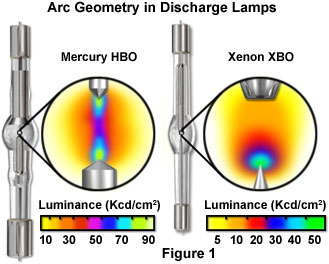
When selecting system components, it is common to question whether an arc lamp can be used in a point-scanning confocal microscope. Although the first confocal microscope, built in the 1950s (and discussed in Marvin Minsky's 1988 memoir), employed a zirconium arc in a prototype stage-scanning instrument, the radiance of short-arc lamps is too low to be useful in modern point-scanning confocal microscopes. Radiance takes into account the size of the source, its angular emission profile, and the light output. The small spot size, low divergence and high radiant flux from even a modest laser cannot be achieved by beam shaping optics applied to an arc-discharge lamp source. Presented in Figure 1 are luminance maps of the plasma ball from mercury (HBO) and xenon (XBO) arc-discharge lamps. Note the variation in flux density from the two sources.
The second issue commonly raised is the suitability of an arc-discharge lamp for use in a spinning disk confocal microscope, and this application is possible, although with limitations. Again, the limiting issue is the radiance of this source type. Since spinning disk confocal microscopes require a large-diameter, well-collimated, uniform beam to simultaneously illuminate many apertures, an arc-discharge lamp has the potential to be an appropriate source. The low transmission of the Nipkow disks employed in present-day spinning disk instruments (typically 1-2 percent) requires considerable input power. Some spinning disk systems utilize an arc lamp to illuminate a Nipkow disk having relatively large apertures, and new designs that increase illumination intensity are emerging.
The widely used spinning disk scanner from Yokogawa utilizes laser light coupled to the scan head by a single mode optical fiber. Additionally, a micro-lens array mounted on a second disk is aligned with the pinholes in the scanner to increase excitation light collection about five-fold compared to devices utilizing a single disk. Losses in the scan head optics, wavelength selection filters, and disk result in an excitation light output to the rear aperture of the objective that is only approximately 5 percent of that measured at the end of the optical fiber. The minimum irradiance at the rear aperture of the objective needed for adequate signal-to-noise ratio in most biological applications is approximately 40 microwatts per square centimeter, although up to 120 microwatts per square centimeter may be utilized. Consequently, about 5 milliwatts intensity is required at the fiber optic output. Such a light output is within the capabilities of some short-arc lamps when they are coupled through a multi-mode fiber or liquid light guide as described below.
Characteristics of Non-Coherent Light Sources
Arc Lamp Emission Wavelengths
In the past, the most frequently utilized wavelengths for fluorescence excitation were the spectral lines produced by the mercury arc (365, 405, 436, 546, and 579 nanometers), as presented in Figure 2. Many fluorophores were therefore selected and used because they were excited by these intense lines, and microscope objectives were designed to give optimal correction for the same wavelengths. As the available laser wavelengths do not often match the mercury emission lines, the microscopist using a laser confocal microscope is sometimes forced to forgo using familiar fluorochromes or to excite them at less than optimal wavelengths. Illustrated in Figure 2 are the spectral irradiance profiles of a typical 100 watt mercury (HBO 100) and 75 watt xenon (XBO 75) arc-discharge lamp as a function of wavelength. The mercury lamp exhibits several peaks in the ultraviolet and visible regions, while the xenon lamp presents an almost continuous spectrum with a very small peak at 467 nanometers and several peaks in the near-infrared region.
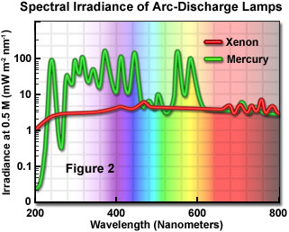
Mercury and Xenon Arc Lamp spectra
The super-pressure xenon arc-discharge lamp is often used when a wide range of excitation wavelengths is required. Its output simulates sunlight because it provides intense broadband illumination without prominent spectral lines in either the ultraviolet or the visible wavelength regions (Figure 2). The pressure-broadened spectral lines match the absorption spectrum of several fluorochromes, resulting in more efficient excitation than that from a narrow laser emission line of equal energy. The availability of broadened spectral lines also allows the simultaneous activation of several fluorochromes with differing emission wavelengths, including those in the ultraviolet.
Coherence
Non-laser light is distinguished from laser light by its much lower degree of coherence. Non-coherent light and coherent light are each limiting theoretical constructs. In widefield microscopy, little attention is paid to the degree of coherence of the illuminating light except when considering diffraction and interference effects. In a practical sense, light is considered to be non-coherent when no speckle effects are present and coherent when they are. Light sources, in fact, exhibit both spatial coherence related to the angular size of the source and temporal coherence related to its wavelength bandwidth. Tungsten filament lamps have relatively low spatial coherence because of the large size of the emitter. Arc lamps possess higher coherence unless a large area of the plasma (see Figure 1) is utilized as the source.
In general, illumination having low coherence is desired for brightfield and reflection optical microscopy modes, while light with higher coherence is required for phase and interference modes. The process of fluorescence involves a sufficient number of steps between excitation and emission that the coherence of the illuminating light is usually unimportant, and the light emitted from the specimen is basically non-coherent.
If the coherence of the illuminating light is too high, images develop fringes caused by interference of the coherent wavefronts reflected from any of the optical surfaces, including the lenses, mirrors, dust windows and, in particular, the cover glass. This complex interference pattern can appear as defined rings, but more commonly, it appears as a high-contrast granular speckle, superimposed upon the image, obscuring details. Furthermore, when the specimen is transparent and has multi-layered microstructure, the speckle spots become more complex figures. Broad-spectrum illuminating light has low temporal coherence, and the speckle averages out. In most situations, illumination with low coherence is preferable for both conventional and confocal microscopy. On the other hand, by adjusting the Köhler illumination system to reduce the effective size of the source, non-laser light sources can also deliver the higher coherence level needed for interference microscopy.
Speckle effects are bright if the interference of light from within the scattering center around a particular point is constructive with that from the background, and dark if destructive interference occurs. The apparent size of the scattering centers and that of the individual speckles are related to the resolution limit (or numerical aperture) of the optics. In the case of non-coherent illumination, overlap between speckle patterns having different wavelengths partially cancel out to produce a lower contrast pattern. Since speckle results from interference phenomena, any movement of the optical system or the specimen will result in a complex change of the speckle pattern in time.
Radiance
Radiance is a measure of the light flux density per unit solid viewing angle. It is expressed in watts per square centimeter per steradian (W/cm^2/sr) and takes into account the radiant flux from the source, its size, and the angular distribution of the light flux. Radiance is independent of the distance from the source because the sampled area increases in proportion. The photometric equivalent measure is the mean or average luminance, often expressed in units of candela per square meter (cd/m^2). Arc lamps are several orders of magnitude more radiant than tungsten filament lamps of comparable wattage, primarily because of the small size of the arc compared to a lamp filament. Tungsten filament lamps can have the filament shaped to permit more efficient use by a light-collection system, and the filaments are often bent into disks or wide, flat bands to match the input aperture of the light-collection optics. Arc lamps generate light from a small torus surrounding the axis between the two electrodes (see Figure 1). An optical collection system is needed not only to project the light source onto the specimen but also to achieve uniform illumination in the specimen plane.
Non-Coherent Light Sources for Optical Microscopy
| Lamp | Radiant Flux (Milliwatts) | Luminous Flux (Lumens) | Spectral Irradiance (Milliwatt/Square Meter/Nanometer) | Source Size (Height × Width in Millimeters) |
|---|---|---|---|---|
| HBO 100 Watts | 3200 | 2200 | 30 (350-700 nm) | 0.25 × 0.25 |
| XBO 75 Watts | 1460 | 1000 | 7 (350-700 nm) | 0.25 × 0.50 |
| Tungsten 100 Watts | 4000 | 2800 | 4.2 × 2.3 | |
| LED (UV, 365 nm) | 100 | 0.1 | 2.5 | 0.25 × 0.25 |
| LED (Violet, 400 nm) | 250 | 3.9 | 6 | 0.9 × 0.9 |
| LED (Blue, 450 nm) | 150 | 116 | 4.5 | 0.9 × 0.9 |
| LED (Green, 520 nm) | 10 | 15.9 | 0.25 | 0.25 × 0.25 |
Table 1
Table 1 compares frequently used light sources for widefield optical microscopes. The HBO 100 (100-watt high-pressure mercury arc-discharge lamp) has the highest radiance (and mean luminance) of the commonly employed lamps of any wattage, due to its very small source size. For the microscopist, the spectral content of the light output (the spectral irradiance), is an important consideration when comparing various sources. Radiant flux is the integral of light output at all wavelengths and does not provide information about its spectral distribution. This is particularly evident when photometric units, such as mean luminance, are used. Since photometric units are weighted according to the spectral sensitivity of the human eye, output in the ultraviolet or infrared has a very small weighting compared to that of green light. Comparisons between the radiant or luminous flux of polychromatic and monochromatic sources (such as lasers and light emitting diodes) are not meaningful if only a limited spectral portion of the output of the polychromatic source is to be utilized.
Only 47 percent of the radiant output from an HBO 100 lamp lies between the wavelengths of 320 and 700 nanometers. Much of that energy is concentrated in the prominent spectral lines at 366 nanometers (approximately 10.7 percent of total), 436 nanometers (12.6 percent), 546 nanometers (7.1 percent), and 579 nanometers (7.9 percent). The usable output from an XBO 75 (75-watt xenon arc lamp), although relatively uniform in the 320 to 700-nanometer range, constitutes only 24.5 percent of the total, with most of the energy falling into the less useful wavelengths in the infrared (approximately 73 percent of the output is at wavelengths longer than 700 nanometers) spectral region.
An XBO 75 (xenon) lamp has a spectral irradiance of approximately 7 milliwatts per meter-squared per nanometer (mW/m^2/nm^1) between 400 and 700 nanometers (see Figure 2). A conventional F/1 mirror reflector-spherical collector lamphouse has a collection efficiency of 12.5 percent, and therefore provides a usable spectral irradiance of about 0.85 milliwatts per nanometer. Thus, if an ideal 20-nanometer band-pass filter is employed, the delivered light flux in the 20-nanometer band would be 17 milliwatts. If the collection mirror used is elliptical rather than spherical, it can capture light from all sides of an arc lamp source, thereby collecting a larger solid angle of the total light emitted. As much as 65 percent of the total emitted light can be collected by such a system, and the radiant flux into large apertures (larger than 5 millimeters) increases up to sevenfold compared to a conventional mirror reflector-spherical collector. Unfortunately, the projected ray bundle has a dark central spot corresponding to the metal end of the lamp, limiting use of this lamp type in microscopy to systems in which the light source is coupled to the microscope by a liquid light guide (further discussion follows).
Stability
Brightness in incandescent sources can be increased by heating the filament to a higher temperature, but this also causes the metal to sublime more rapidly, darkening the glass envelope and causing the filament to burn out. The halogen gas in the quartz-halogen lamp interrupts this process by first reacting with the evaporating tungsten to form tungsten-halide compounds, which then decompose when they strike the hot filament. These two processes combine to effectively return the tungsten to the filament, and thereby permit it to be operated at a higher temperature without darkening the lamp envelope, and for reasonable filament lifetimes. When powered by a regulated power supply, the consistent envelope transparency results in a constant lamp output level, which is sufficiently stable to be useful for photometric measurements.
In general, arc lamps are less stable than filament lamps because the gas plasma is unstable and affected both by magnetic fields and by the erosion of the electrodes. The intensity of the xenon arc can be deeply and rapidly modulated in time to keep the electrodes cool, as is the case in an electronic flash unit for photography. Alternatively, the position of the arc plasma can be stabilized either by a periodic magnetic field imposed by a rotating permanent magnet or by superimposition of a small alternating electric current on the main direct excitation current. The addition of a heating coil that surrounds a portion of the HBO 100 arc allows the current through the lamp to be varied over a wide range while stabilizing the output intensity.
Light Emitting Diodes
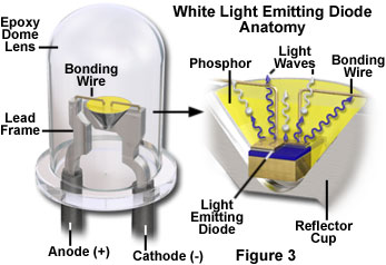
Light emitting diodes (LEDs) comprise a unique category of non-coherent light source with characteristics that are distinct from those of arc or tungsten filament lamps. LEDs produce continuous light efficiently from a simple twin-element semiconductor diode encased in a clear epoxy dome that acts as a lens (see Figure 3). One of the two semiconductor regions that comprise the junction in the chip is dominated by negative charges (n region), and the other is dominated by positive charges (p region). When a sufficient voltage is applied to the electrical leads, a current is created as electrons move across the junction from the n region into the p region where the negatively charged electrons combine with positive charges. Each combination of charges is associated with an energy level reduction that may release a quantum of electromagnetic energy in the form of a photon. The energy of emitted photons is characteristic of the semiconductor material, and consequently, different colors are achieved by making changes in the semiconductor composition of the chip.
Photon-emitting diode p-n junctions are typically based on a mixture of Group III and Group V elements, such as gallium arsenide, gallium arsenide phosphide, and gallium phosphide. Careful control of the relative proportions of these compounds, and others incorporating aluminum and indium, as well as the addition of dopants such as tellurium and magnesium, enables manufacturers and researchers to produce diodes that emit red, orange, yellow, or green light (see Table 2). The bandwidth of these emissions is typically between 12 and 40 nanometers with no significant components of infrared or ultraviolet wavelengths. Recently the use of silicon carbide and gallium nitride has permitted blue-emitting diodes to be introduced, and combining several colors in various combinations provides a mechanism to produce white light.
As illustrated in Figure 3, light emerges from the sides of the light emitting diode semiconductor chip and is reflected forward by a cup that is joined into the end of one electrode (the cathode) while the top face of the chip is connected with a gold bonding wire to a second electrode (anode). The typical diode semiconductor chip measures approximately 0.25 millimeters-square, and the epoxy body ranges from 2 to about 10 millimeters in diameter. Most commonly, the body of a light emitting diode lamp is round, but they may be rectangular, square, or triangular. The angle of the light cone emitted by the diode-reflector cup combination can be altered by changing the epoxy lens shape, the geometry of the reflector cup, and the size and distance between the semiconductor diode and the nose of the epoxy lens. Clear epoxy lenses produce the highest radiance when their output is limited to approximately a 15-degree angle.
Light Emitting Diode Color Variations
| Color Name | Wavelength (Nanometers) | Semiconductor Composition |
|---|---|---|
| Infrared | 880 | GaAlAs/GaAs |
| Ultra Red | 660 | GaAlAs/GaAlAs |
| Super Red | 633 | AlGaInP |
| Super Orange | 612 | AlGaInP |
| Orange | 605 | GaAsP/GaP |
| Yellow | 585 | GaAsP/GaP |
| Incandescent White | 4500K (CT) | InGaN/SiC |
| Pale White | 6500K (CT) | InGaN/SiC |
| Cool White | 8000K (CT) | InGaN/SiC |
| Pure Green | 555 | GaP/GaP |
| Super Blue | 470 | GaN/SiC |
| Blue Violet | 430 | GaN/SiC |
| Ultraviolet | 395 | InGaN/SiC |
Table 2
Although there have been past efforts to employ light emitting diodes as light sources for microscopy, they failed because of the low radiant output of early devices. Previously patented designs for microscope illumination employed large numbers of LEDs grouped to produce a uniform pattern of illumination. This approach produced a higher radiant flux but failed to address the low radiance that results from such a large, distributed source. Present day LEDs are sufficiently bright to function individually as an effective source of monochromatic light for fluorescence or transmitted light microscopy. While their spectral irradiance is still lower than that of the spectral peaks from the HBO (mercury) 100 arc lamp, it is approaching that of the XBO (xenon) 75 lamp in the visible spectrum.
Light emitting diodes are more efficient than arc-discharge lamps at converting electricity into visible light, achieving outputs of up to 100 lumens per watt compared to the 22 lumens per watt for an HBO 100 source. LEDs are rugged and compact, and can often last 100,000 hours in use, or about 500 times longer than an HBO 100. Green LEDs may have conversion efficiencies as high as 74 percent. Violet and blue LEDs with light outputs of 250 and 150 milliwatts are now commercially available. Light emitting diode output may be modulated at high frequencies (10 megahertz, MHz) and their output brightness may be regulated by limiting the available current, features that eliminate the need for mechanical shutters and neutral density filters in microscopy applications.
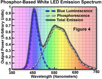
LEDs are fundamentally monochromatic emitters, and high-brightness, single-color lamps are the most widely used of the current generation of devices. There are two principal approaches for producing white light from devices that are fundamentally monochromatic. One method is based on combining three different diode colors in one envelope, or different materials in a single LED, in such proportion that the output appears white; another technique is to utilize a violet or ultraviolet emitting diode to provide energy for excitation of a phosphor that emits white light (as illustrated in Figure 4).
Collecting and Relaying Light to the Specimen
All scanning mechanisms for confocal microscopy employ an illumination method that fills the rear aperture of the objective. Coupling the available light from a light source to the specimen is somewhat more involved in the non-laser case, since sources such as arc lamps radiate into a sphere rather than producing a parallel beam. Consequently, reflectors are required to direct light from the "backside" of the arc toward the specimen. Unneeded wavelengths, such as infrared and ultraviolet, can be allowed to pass through dichromatic mirrors (an infrared transmitter is denoted a "cold mirror" and an ultraviolet transmitter a "hot mirror") and be absorbed in the lamp housing. The dissipation of heat by a cold mirror reduces source movement caused by thermal expansion of the mechanical and optical components. Lenses near hot sources must be mounted appropriately to allow for thermal expansion.
Köhler illumination is the most common optical illumination scheme in both transmitted and reflected light microscopy since it serves to uniformly illuminate the image field from a spatially complex source by imaging only a portion of the source at the focal plane of the condenser (or the objective rear focal plane in epi-illumination). The light striking the specimen is even, although this light may not arrive from all possible angles with equal distribution. The field aperture (which effectively lies in an intermediate image plane) is imaged onto the specimen to limit the area illuminated without affecting the angle of the illuminating light. In the case of highly non-uniform sources, a diffuser may be used to further improve uniformity at the focal plane. Köhler illumination is not the most efficient system because it does not make use of the full surface of the source or the full angular distribution of the emitted light.
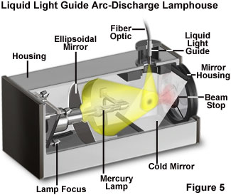
A major function of Köhler illumination systems is to ensure uniform illumination and to control its coherence; however, it is possible to achieve homogeneous illumination using a light guide. Scrambling of the light, effectively decreasing its spatial or temporal coherence, is also accomplished by the application of light guides. The most widely used and practical method of coupling a light source to the microscope, while also reducing coherence, is to focus the light into a flexible length of single-mode optical fiber or a liquid light guide (Figure 5). Thermal motion in the liquid light guide constantly alters the optical path and scatters light so that both spatial and temporal coherence are effectively eliminated.
In the case of a coiled single-mode optical fiber, the reflections from the cladding constantly change because the fiber flexes slightly, producing an exit beam that is effectively uniform in intensity over time and space. The technique of vibrating the fiber at a frequency of up to 100 kilohertz has been reported to be effective in light scrambling as well. The phase of the light is scrambled due to the varying path lengths of light waves passing through the fiber, although the high radiance and monochromaticity are preserved. The exit beam is described by a "top-hat" intensity profile rather than the Gaussian profile that is characteristic of laser light.
To avoid possible heat damage to the light scrambler, infrared radiation as well as other unwanted emission wavelengths should be removed before they enter the fiber or light guide. Ideally, only wavelengths critical to image formation should leave the light source. Rather than relying on broadband mirrors, cold mirrors and band-pass interference filters should be employed to select the light wavelengths transmitted to the aperture disk and to allow unwanted heat to escape.
A critical issue is the efficiency of coupling the source lamp output into the optical fiber. Most fibers have a numerical aperture between 0.2 and 0.55, and this value should be matched to the collection optics for the source. Several manufacturers provide lamphouses designed for implementation with liquid light guides in which this condition is met. The combination of a 75-watt xenon arc in an elliptical reflector, a cold mirror, and an optically matched 3 to 5 millimeter-diameter liquid light guide can deliver a light output in excess of 2 milliwatts per nanometer (see Figure 5). The fiber end becomes the effective light source for the microscope regardless of the size of the lamp arc, resulting in a decrease in radiance compared to the arc itself. However, when the goal is uniform illumination of a large-diameter aperture, as is the case in the disk scanning confocal instrument, an extended source is not as detrimental to performance. The only requirement is a collimating lens of sufficient diameter to efficiently collect the output from the light guide and project it onto the disk scanner.
Spinning Disk Confocal Microscope Light Budgets
| Coherent Source (Argon-Ion Laser at 488 Nanometers) | |
|---|---|
| Radiant Flux at Single Mode Fiber Output | 9 Milliwatts |
| Irradiance at Objective Aperture | 120 Microwatts per Square Centimeter |
| Non-Coherent Source (XBO 75 Lamp, 5 Millimeter Liquid Light Guide, and 20 Nanometer Bandpass Filter) | |
| Radiant Flux at Liquid Light Guide Output | 28.5 Milliwatts |
| Irradiance at Objective Aperture | 36 Microwatts per Square Centimeter |
Table 3
Table 3 summarizes typical results experienced with non-coherent and coherent illumination of a Yokogawa spinning disk confocal instrument. In this specific configuration, the coherent illumination system consists of a multi-line laser coupled through an acousto-optic tunable filter (AOTF) to a single-mode optical fiber. The output of this fiber is a Gaussian beam of 0.3 numerical aperture, which is subsequently shaped and expanded to a uniform beam 14.5 millimeters in diameter. This expanded beam is reflected by a mirror through a path that allows the introduction of an external filter slider or wheel for wavelength selection. By introducing a mirror and wavelength-selective filter in place of the filter slider, it becomes possible to introduce the expanded and collimated output from a liquid light guide coupled to an XBO 75 lamp mounted in an elliptical reflector. To produce a 20-millimeter diameter beam of uniform intensity, the output from the fiber is collimated with a plano-convex lens. The standard red-green-blue (RGB) dichromatic mirror of the Yokogawa confocal microscope allows three wavelengths, each of 20-nanometer bandwidth, to be transmitted. Table 3 compares the light flux to the rear aperture of the objective for both sources with excitation in the blue-light spectral region (488-nanometer laser line and 470 to 490-nanometer arc lamp output). The light flux values clearly demonstrate that the non-coherent source can provide sufficient energy for this application.
Taking full advantage of a polychromatic source in a spinning disk confocal microscope requires a wide range of wavelength-selective filters and dichromatic mirrors. Although the filters are readily available, the dichromatic mirrors used in the Yokogawa instrument are unusual in design and limited in availability. At present, lack of a greater range of suitable dichromatic mirrors prevents full utilization of an arc source in this device.
Consideration of the illumination properties of current devices indicates that a light emitting diode would also be suitable in this spinning disk application. Coupling a single LED to a multi-mode optical fiber or liquid light guide is a simple matter, and can readily be accomplished by positioning the LED at the rear aperture of an inexpensive low-power objective (such as a 10x achromat) to couple the light into the fiber. Most LEDs have an output bandwidth of 20-40 nanometers, so at least half of the light output would pass through the 20-nanometer bandwidth of the dichromatic mirror. Based on the previously discussed measurements of light losses in the Yokogawa scanner, about 1-2 milliwatts must reach the spinning disk to achieve the requisite 40 microwatts per square-centimeter at the objective rear aperture. Thus, a 10-milliwatt monochromatic-output light emitting diode would probably suffice. However, if a polychromatic LED source is necessary, present day white LEDs lack the output power and uniform spectral radiance that are needed.
Conclusion
Non-coherent illumination sources are infrequently used in spinning disk confocal microscopes, although most confocal instruments are equipped with an arc lamp for widefield visual observation of specimens. A review of the characteristics of short-arc lamps illustrates that they can be effectively employed in the appropriate spinning disk confocal microscope. In addition, it is likely that light emitting diodes will provide inexpensive, stable, efficient, and long-lived illumination in both widefield and disk-scanning confocal microscopy.