The Berek compensator is an optical device that is capable of quantitatively determining the wavelength retardation of a crystal, fiber, mineral, plastic film or other birefringent material. Provided the thickness of the material can be measured, a Berek compensator can be utilized to ascertain the birefringence value. The compensator operates by measuring the rotation angle of a calcite or magnesium fluoride optical plate cut perpendicular to the optical microscope axis.
In a Berek compensator adjusted for zero retardation, the single birefringent uniaxial crystalline plate is oriented with the extraordinary optical axis perpendicular to the surface of the crystal and parallel to the microscope optical axis. Polarized light passing through the specimen encounters the compensator at normal incidence (zero degrees) and propagates through the compensator with a velocity that is independent upon the direction of polarization. In other words, the Berek compensator acts as an ordinary isotropic material when the birefringent plate is perpendicular to the microscope optical axis, and thus, has no effect on polarized light passing through.
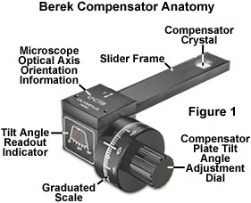
As the compensator plate tilt adjustment dial is rotated (see Figure 1) with respect to the direction of incident polarized light (and microscope optical axis), the incident plane coincides with the refractive index plane of the extraordinary axis and alters the velocity of light passing through the crystal. In general, the polarized wavefront is retarded by a measurable quantity that is dependent upon the angle of tilt and the wavelength of illumination. Simultaneously, light polarized perpendicular to the incident plane continues to propagate through the compensator plate along the ordinary axis and with a velocity that remains independent upon the tilt angle. As a net result, polarized light exiting the specimen and passing through a tilted Berek compensator is retarded by an additional amount by the compensator and accumulates a relative phase shift (dependent upon the tilt angle), which can be measured with the device. The degree of optical path difference introduced by a Berek compensator is determined by the thickness of the birefringent plate, the wavelength of illumination, the refractive index difference between the ordinary and extraordinary axes of the compensator crystal, and the tilt angle. Most manufacturers compound all of these quantities into a constant that is utilized to calibrate the retardation vernier scale.

Max Berek developed this style of polarization compensator in 1913 as a variable waveplate that can impose a quarter or half-wave retardation at any wavelength between 200 and 2800 nanometers (5 wavelengths), dramatically reducing the number of compensation plates necessary for quantitative polarized light microscopy. Subsequent design improvements enable the measurement of retardation values between a range of zero and 11,000 nanometers (20 wavelengths) for measurements of very high retardation values. As discussed above, the original Berek compensator consisted of a single cut plate of uniaxial birefringent material (calcite or magnesium fluoride) having an extraordinary optical axis perpendicular to the long dimension of the plate frame (Figure 1). The birefringent plate is tilted about the horizontal axis by means of a calibrated micrometer drum to enable precise measurements of retardation.
As illustrated in Figures 1 and 2, the Berek compensator is equipped with a tilting calcite plate housed in a rectangular frame and controlled by a rotating drum knob affixed to a vernier scale. The compensator is positioned in the microscope intermediate tube at a 45-degree angle with respect to the polarization directions of the polarizer and analyzer, and the retardation is varied by turning the compensator knob. Rotating the vernier dial on the compensator inclines the birefringent plate relative to the microscope optical axis (see Figure 2(a)). As the plate is tilted, the retardation value is increased
In practice, a birefringent specimen (usually a crystal) is placed on the microscope stage and rotated until it attains the extinction position (where the features of interest become dark). Next, the stage is rotated +45-degrees and clamped into place. The compensator drum knob is set to a position of 30-degrees (turning the knob in a single direction to avoid backlash) and inserted into the microscope intermediate tube. Finally, the compensator knob is rotated to confirm that the black fringe intersects the center of the field of view. If the fringe does not intersect the center, the stage is rotated by 90-degrees and re-clamped. An interference filter having a transmission bandwidth between 540 and 570 nanometers will improve the accuracy of measurements, but also produces multiple black fringes in addition to the one that is visible in the absence of the filter. A reference table gives the optical path differences for the tilt angle in which compensation is achieved.
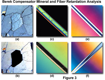
A series of typical measurements conducted with a Berek compensator are presented in Figure 3. The mineral thin section in Figure 3(a) illustrates how the grain structure appears under crossed polarized illumination either without a compensator or when the retardation plate is perpendicular to the optical axis (no retardation). By inserting the Berek compensator and rotating the vernier dial, the central grain is brought to extinction (Figure 3(b)) and a measurement of birefringence can be obtained. A typical analysis of Ramie fiber thickness is presented in Figures 3(c) and 3(d) for crossed polarized light alone (Figure 3(c)), and with the compensator inserted and the retardation plate tilted at the proper angle for maximum extinction of the fiber (Figure 3(d)).
Similarly, other birefringent fibers can also be evaluated with a Berek compensators over a wide range of retardation values (Figures 3(e) and 3(f)). The synthetic fiber illustrated in Figure 3(e) exhibits positive birefringence, and displays an evenly distributed extinction band in the central portion with higher order background interference colors when a low-value retardation (0-3 wavelengths) Berek compensator is inserted into the light path. Alternatively, a high-value compensator (0-20 wavelengths) produces a skewed extinction band inside the fiber and lower-order interference patterns in the background (Figure 3(f)). Note that for fibers exhibiting negative birefringence, the interference fringe order would be reversed in Figures 3(e) and 3(f). In general, Berek compensators having a low retardation measurement range are built with calcite/magnesium fluoride plate, while compensators designed to measure high retardation values are constructed with calcite plates.