Illumination of the specimen is the most important variable in achieving high-quality images in microscopy and critical photomicrography. Köhler illumination was first introduced in 1893 by August Köhler of the Carl Zeiss corporation as a method of providing the optimum specimen illumination.
This technique is recommended by all manufacturers of modern laboratory microscopes because it can produce specimen illumination that is uniformly bright and free from glare, thus allowing the user to realize the microscope's full potential.
The manufacturers have designed modern microscopes so that the collector lens and any other optical components built into the base of the microscope will project an enlarged and focused image of the lamp filament onto the plane of the aperture diaphragm of a properly positioned substage condenser. Closing or opening the condenser diaphragm controls the angle of the light rays emerging from the condenser and reaching the specimen from all azimuths. Because the light source is not focused at the level of the specimen, the light at specimen level is essentially grainless and extended and does not suffer deterioration from dust and imperfections on the glass surfaces of the condenser. Opening and closing of the condenser aperture diaphragm controls the angle of the light cone reaching the specimen. The setting of the condenser's aperture diaphragm, along with the aperture of the objective, determines the realized numerical aperture of the microscope "system". As the condenser diaphragm is opened, the working numerical aperture of the microscope increases, resulting in greater resolving power and light transmittance. Parallel light rays that pass through and illuminate the specimen are brought to focus at the back focal plane of the objective, where the image of the variable condenser aperture diaphragm and the image of the light source will be seen in focus.
Condenser Aperture Diaphragm
Discover how the condenser aperture diaphragm controls the illuminating light cone.
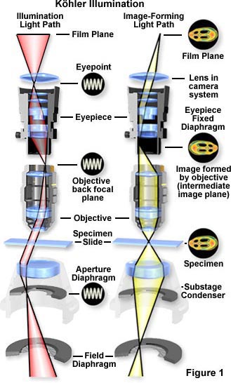
The light pathways illustrated in Figure 1 are schematically drawn to represent separate paths taken by the specimen illuminating light rays and the image-forming light rays. This is not a true representation of any real segregation of these pathways, but a diagrammatic representation presented for purposes of visualization and discussion. Figure 1(a) shows the ray paths for illuminating light produce a focused image of the lamp filament at the plane of the substage condenser aperture diaphragm, the back focal plane of the objective, and the eyepoint (also called the Ramsden disk) of the eyepiece. These areas that are in common focus are often referred to as conjugate planes, which are critical in achieving proper Köhler illumination. By definition, an object that is in focus at one plane is also in focus at the other conjugate planes of that light path. In each light pathway (both image-forming and illumination), there are four separate planes that together make up the conjugate plane set.
Conjugate planes in the path of the illuminating light rays in Köhler illumination (Figure 1(a)) include:
- The lamp filament.
- The condenser aperture diaphragm (at the front focal plane of the condenser).
- The back focal plane of the objective.
- The eyepoint (also called the Ramsden disk) of the eyepiece, which is located approximately one-half inch (one centimeter) above the top lens of the eyepiece, at the point where the observer places the front of the eye during observation.
Likewise, the conjugate planes in the image-forming light path in Köhler illumination (Figure 1(b)) include:
- The field diaphragm.
- The focused specimen.
- The intermediate image plane (i.e., the plane of the fixed diaphragm of the eyepiece).
- The retina of the eye or the film plane of the camera.
Conjugate focal planes are often useful in troubleshooting a microscope for contaminating dust, fibers, and imperfections in the optical elements. If these artifacts are in sharp focus, it follows that they must reside on or near a surface that is part of the imaging-forming set of conjugate planes. Members of this set include the glass element at the microscope light port, the specimen, the reticle in the eyepiece, and the bottom lens element of the eyepiece. Alternatively, if these contaminants are fuzzy and out of focus, look for them near the illuminating set of elements that share conjugate planes. Suspects in this category are the condenser top lens (where dust and dirt often accumulate), the exposed eyepiece lens element (contaminants from eyelashes), and the objective front lens (usually fingerprint smudges).
Conjugate Planes
Explore how conjugate planes pass through focus in the microscope light path.
Figure 2 illustrates a typical microscope setup where the lamp housing (illumination source) is attached to the base and projects light through several lenses and then through the substage condenser after being reflected by a mirror in the microscope base. The light source itself should be precentered or centerable to the optical axis of the microscope. Light emitted from the tungsten-halogen lamp filament first passes through the collector lens located close to the lamp housing, and then through a second lens that is closer to the field diaphragm. Often, a sintered or frosted glass filter is placed between the lamp and the collector lens to diffuse the light and ensure an even intensity of illumination. In practice, the image of the lamp filament is focused onto the front focal plane of the condenser while the diffuser glass is temporarily removed from the light path. The focal length of the collector lens must be carefully matched to the lamp filament dimensions to ensure that a filament image of the appropriate size is projected into the condenser aperture. For proper Köhler illumination, the image of the filament should completely fill the condenser aperture.
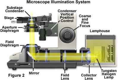
The second lens in the light path is called the field lens, which is responsible for bringing the image of the filament into focus at the plane of the substage condenser aperture diaphragm. Focused light leaving the field lens is reflected by a mirror (positioned at a 45-degree angle to the light path) through the field diaphragm and into the substage condenser. The field diaphragm serves as a virtual source of light for the microscope and its image is focused by the condenser onto the specimen plane. Optical designs for the arrangement of these elements may vary by microscope manufacturer, but the field diaphragm should be positioned at a sufficient distance from the field lens to eliminate dust and lens imperfections from being imaged in the plane of the specimen.
Transmitted Microscopy Light Pathways
Discover how the condenser and field diaphragms affect illumination in transmitted microscopy.
The field diaphragm in the base of the microscope controls only the width of the bundle of light rays reaching the condenser--it does not affect the optical resolution, numerical aperture, or the intensity of illumination. Proper adjustment of the field diaphragm (i.e., centered in the optical path and opened so as to lie just outside of the field of view) is important for preventing glare than can reduce contrast in the observed image. The elimination of excess light is particularly important when attempting to image samples with inherently low contrast. When the field diaphragm is opened too far, scattered light originating from the specimen and light reflected at oblique angles from optical surfaces can act to degrade image quality.
The substage condenser is typically mounted directly beneath the microscope stage in a bracket that can be raised or lowered independently of the stage by rotating a knurled knob, as illustrated in Figure 2. The aperture diaphragm is opened and closed with either a swinging arm, a lever, or by rotating a collar on the condenser housing. It should be noted that correct adjustment of the substage condenser is probably the most critical aspect of achieving proper Köhler illumination. Unfortunately, however, condenser misalignment and improperly adjusted condenser aperture diaphragms are the main source of image degradation and poor quality photomicrography.
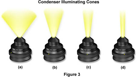
When properly adjusted, light from the condenser will fill the back focal plane of the objective with image-forming light by projecting a cone of light to illuminate the field of view (A thorough discussion of substage condensers is included in another section of the primer). The condenser aperture diaphragm is responsible for controlling the angle of the illuminating light cone and, consequently, the numerical aperture of the condenser. This concept is illustrated in Figure 3, where a series of condensers are illustrated with light cones (and numerical apertures) of decreasing size from left to right in the figure. Condenser light cone shapes are also a function of the degree of correction for optical aberration as demonstrated in the interactive Java tutorial below:
Condenser Light Cone Shapes
Discover how the degree of optical correction affects condenser light cone shape.
Figure 3(a) illustrates a condenser of numerical aperture approximately 1.20, which has a broad light cone allowing imaging of the specimen with high numerical aperture objectives. Figures 3(b-d) show how reducing the size of the aperture diaphragm will produce a corresponding decrease in the light cone size and numerical aperture (Figure 3(b) NA = 0.60; Figure 3(c) NA = 0.30; Figure 3(d) NA = 0.15). We have also constructed an interactive Java tutorial that demonstrates how the condenser light cone size and shape varies with numerical aperture.
Condenser Light Cones
Study how aperture diaphragm size affects the size and shape of condenser light cones.
It is important to note, with respect to the size and shape of condenser light cones, that reducing the size of the field diaphragm only serves to slightly decrease the size of the lower portions of the light cones illustrated in Figure 3. The angle and numerical aperture of the light cone remains essentially unchanged with reduction in field diaphragm size. Another important concept, often overlooked by novices, is that the intensity of illumination should not be controlled through opening and closing the condenser aperture diaphragm, nor by shifting the condenser axially with respect to the optical center of the microscope. Illumination intensity should only be controlled through the use of neutral density filters placed into the light path or by reducing voltage to the lamp (although the latter is not usually recommended, especially for photomicrography). To ensure the maximum performance of the tungsten-halogen lamp, refer to the manufacturer's instrument manual to determine the optimum lamp voltage (usually 6-10 volts) and use that setting. Brightness of the illumination can then be easily controlled by adding or removing neutral density filters.
Condenser Aperture Diaphragm Operation
Explore how the substage condenser aperture controls illumination entering the objective.
The size of the substage condenser aperture diaphragm should not only coincide with the desired numerical aperture, but also the quality of the resulting image should be considered. Generally, the aperture diaphragm should be adjusted to provide sufficient image contrast without being closed to the point of introducing a loss of resolution and detail. Refractive index and inherent specimen contrast are very important in determining the size of the aperture diaphragm. In general, the diaphragm should be set to a position that allows 60 to 90 percent of the entire light disc size (visible in the eye tube after removal of the eyepiece or with a Bertrand lens), although this may vary with extremes in specimen contrast.
The effects of condenser aperture setting on the quality of images captured by photomicrography are illustrated in Figure 4. The specimen is a thin section of Tilia (Basswood) stem stained with Fast Green and Eosin and photographed on Fujichrome 64T transparency film using a 40x Planachromat objective (NA = 0.75) and a swing-out top lens achromatic condenser (NA = 0.90). The approximate condenser aperture opening settings are: Figure 4(a) - 90 percent (NA = 0.81); Figure 4(b) - 60 percent (NA = 0.54); Figure 4(c) - 20 percent (NA = 0.18). The tissue section is selectively color stained to reveal fine detail and differentiate sub-cellular components for observation.
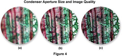
In Figure 4(a), where the aperture diaphragm is set to a position in which the numerical aperture of the condenser and objective are nearly equal, much of the fine specimen detail is visible, although there remains a considerable amount of scattering and glare. The image is also significantly brighter than its counterparts, which were made with a smaller setting of the aperture diaphragm. Figure 4(b) illustrates the Tilia stem at a condenser aperture size that produces a numerical aperture approximately 70 percent that of the objective. Glare is reduced, the image is very sharp, and fine image detail is present without significant diffraction artifacts. For this specimen, the photomicrograph in Figure 4(b) represents the optimum setting for the condenser aperture diaphragm. When the diaphragm is closed to the smallest setting at about 25 percent of the objective numerical aperture (Figure 4(c)), fine image details become obscured with diffraction artifacts and refraction phenomena. The image also takes on a darker overall cast that produces shifts in the color hues of the specimen. This concept can be explored in greater detail using the interactive Java tutorial on the substage condenser aperture diaphragm.
Condenser Effects on Image Contrast
Discover how the size of the condenser aperture affects specimen image contrast.
From the above discussion it is evident that the condenser aperture diaphragm should be set to a position that will provide a compromise mixture of direct and deviated light that depends, to a large degree, on the absorption, diffraction, and refraction characteristics of the specimen. This must be accomplished without overwhelming the image with artifacts that obscure detail and present erroneous enhancement of contrast. The amount of image detail and contrast necessary to produce the best photomicrograph is also dependent upon refractive index, optical characteristics and other specimen-dependent parameters.
When the aperture diaphragm is erroneously closed too far, deviated light begins to obscure direct illuminating rays, resulting in diffraction artifacts that cause visible fringes, banding, and/or pattern formation in photomicrographs. Other problems, such as refraction phenomena, can also produce apparent structures in an image that are not real. Alternatively, opening the condenser aperture too wide causes unwanted glare and light scattering from the specimen and optical surfaces within the microscope. This leads to a significant loss of contrast and washing out of image detail. The correct setting will vary from specimen to specimen, and the experienced microscopist will soon learn to accurately adjust the condenser aperture diaphragm (and numerical aperture of the system) by observing the image without having to view the diaphragm in the back focal plane of the objective. In fact, many microscopists believe that critical reduction of the numerical aperture of the microscope system to optimize image quality is the single most important step in photomicrography.
The illumination system of the microscope, when adjusted for proper Köhler illumination, must satisfy several requirements. The illuminated area of the specimen plane must be at least as large as the field of view for any given objective. Also, the light must be of uniform intensity and the numerical aperture must vary from a maximum (equal to that of the objective) to a minimum value that will depend upon the optical characteristics of the specimen. Table 1 contains a list of objective numerical apertures versus the field of view diameter (for an eyepiece of field number 18) for each objective, ranging from very low to very high magnifications.
| Objective Designation | Numerical Aperture | Field of View Diameter |
|---|---|---|
| Planachromat 1x | 0.04 | 18.0 |
| Planachromat 2x | 0.06 | 9.0 |
| Planachromat 4x | 0.10 | 4.50 |
| Planachromat 5x | 0.15 | 3.60 |
| Planachromat 10x | 0.25 | 1.80 |
| Planachromat 20x | 0.40 | 0.90 |
| Planachromat 40x | 0.65 | 0.45 |
| Planapochromat 50x | 0.90 | 0.36 |
| Planapochromat 60x | 0.95 | 0.30 |
| Planapochromat 100x | 1.40 | 0.18 |
Table 1
From the data presented in Table 1, it is obvious that the variation in field of view diameters is 100-fold going from the 1x Planachromat to the 100x Planapochromat. This yields an amazing 10,000-fold difference in the area of illumination between the 1x and 100x objectives. Such a wide range of illumination areas requires adjustments to many components in the optical path in order to accommodate all magnifications. These calculations were made assuming an eyepiece field number of 18, but many modern microscopes are equipped with wide field eyepieces having field numbers of 20 or 25. The field of view diameter (as given in column three of Table 1) can be recalculated for any eyepiece using the following formula:
where D is the diameter of the field of view, FN is the eyepiece field number, and M is the objective magnification.
Modern microscopes are equipped with specialized substage condensers that have a swing-out lens, which can be removed from the optical path for use with lower power objectives (2x through 5x). This changes the performance of the remaining components in the light path, and some adjustment is necessary to achieve the best illumination conditions. The field diaphragm can no longer be used for alignment and centering of the substage condenser and is now ineffective in limiting the area of the specimen under illumination. Also, much of the unwanted glare once removed by the field diaphragm is reduced because the top lens of the condenser produces a light cone having a much lower numerical aperture, allowing light rays to pass through the specimen at much lower angles. Most importantly, the optical conditions for Köhler illumination no longer apply.
Alignment of the microscope optical components and the establishment of Köhler illumination conditions should always be undertaken at a higher (10x) magnification before removing the swing-out condenser lens for work at lower (5x and below) magnifications. The height of the condenser should then not be changed. Condenser performance is radically changed when the swing-out lens is removed. The image of the lamp filament is no longer formed in the aperture diaphragm, which ceases to control the numerical aperture of the condenser and the illumination system. In fact, the aperture diaphragm should be opened completely to avoid vignetting, a gradual fading of light at the edges of the viewfield.
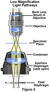
The modified optical pathway for transmitted light in a low power microscope system is illustrated in Figure 5. The field diaphragm is now positioned in the correct plane to act as an aperture stop to control the numerical aperture and the size and shape of the light cone for the illuminating and image-forming light rays passing through the condenser. The specimen plane is fully illuminated with equiangular cones (as in Köhler illumination), however the filament is now imaged at back lens mount of the objective instead of the back focal plane.
It is important to note that the image of the field diaphragm is no longer formed in the specimen plane, although the overall intensity of illumination is still uniform within the field of view, provided the lamp condenser lens is slightly diffusing (chemically etched) or frosted. The new duties of the field diaphragm in low magnification microscopy are the topic of an interactive Java tutorial on specimen contrast adjustment at low magnifications.
Specimen Contrast at Low Magnifications
At low magnifications, the field diaphragm acts as the microscope aperture stop to control numerical aperture and specimen contrast.
Start Tutorial »Contrast adjustment in low magnification microscopy is similar to the procedure using high magnification objectives, as illustrated in Figure 4. When the field diaphragm is wide open (greater than 80 percent), specimen details are washed out and a significant amount of scattering and glare is present. Closing the field diaphragm to a position between 50 and 80 percent will yield the best compromise on specimen contrast and depth of field. Objectives designed for low magnification are significantly simpler in design than their higher magnification counterparts. This is due to the smaller angles of illuminating light cones produced by low magnification condensers, which require objectives of lower numerical aperture.
Measurement reticles, which must be in sharp focus and superimposed on the specimen image, can be inserted into several of the conjugate planes discussed above. The most common eyepiece (ocular) measuring and photomicrography reticles are placed in the intermediate image plane, which is a fixed aperture diaphragm within the eyepiece. It is theoretically possible to also place reticles in the specimen plane or in the plane of the illuminated field diaphragm. Stage micrometers are specialized "reticles" placed on microslides, which are used to calibrate eyepiece reticles and to make specimen measurements. Placing reticles in the plane of the field diaphragm is never done (to our knowledge) and would require a condenser of very high correction for aberration to completely eliminate artifacts and provide a sharp image for measurement.
Both color and neutral density filters are often placed within the optical pathway to reduce light intensity and alter the color characteristics of the illumination. There are several locations within the microscope stand where these filters are usually placed. Some modern laboratory microscopes have a filter holder sandwiched between the lamp housing and collector lens, which serves as an ideal location for these filters. Often, neutral density filters along with color correction filters and a frosted diffusion filter are placed together in this filter holder. Other microscope designs provide a set of filters built internally into the body which can be toggled into the light path by means of a lever. A third common location for filters is a holder mounted on the bottom of the substage condenser, significantly lower than the aperture diaphragm, that will accept gelatin or glass filters.
It is important not to place filters in or near any of the image-forming conjugate planes to avoid dirt or surface imperfections on the filters to be imaged along with the specimen. Some microscopes have an attachment for placing filters near the light port at the base (near the field diaphragm). This placement is probably too close to the field diaphragm, and surface contamination may be either in sharp focus or appear as blurred artifacts superimposed onto the image. It is also not wise to place filters directly on the microscope stage for the same reasons.
For further reading, we invite visitors to peruse our Bibliography, where numerous citations refer to excellent books dealing with various topics in microscope illumination and the Köhler technique. We have also described how to adjust both transmitted and reflected microscopes for Köhler illumination.