The mechanical tube length of an optical microscope is defined as the distance from the nosepiece opening, where the objective is mounted, to the top edge of the observation tubes where the eyepieces (oculars) are inserted. The drawing in Figure 1 illustrates the optical path (the red line) defining the mechanical tube length for a typical transmitted light microscope.
For many years, almost all prominent microscope manufacturers designed their objectives for a finite tube length. The designer proceeded under the assumption that the specimen, at focus, was placed at a distance a "little" further than the front focal plane of the objective. The objective then projects a magnified image of the specimen which converges (is brought into focus) at the level of the eyepiece diaphragm, located ten millimeters below the top edge of the openings of the microscope observation tube--where the eyepieces are inserted (see Figures 1 and 2).
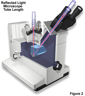
Tube length has now been standardized to the Royal Microscopical Society (RMS) suggestion of 160 millimeters for finite-corrected transmitted light microscopes. Objectives designed for a 160 millimeter finite tube length microscope bear the inscription "160" (mm) on the barrel as outlined in our discussion on objective specifications and identification. The positioning of the ocular and objectives is reversed in metallographs, which are essentially inverted reflected light microscopes as illustrated in figure 2. Note that in both the examples depicted in Figures 1 and 2, the "tube" is not a straight line and the light waves are transmitted from the objectives to the eyepieces (oculars) with mirrored beamsplitters. This is the case with most modern microscopes, especially those equipped with trinocular heads for photomicrography.
Some older microscopes have mechanical tube lengths that deviate from the 160 millimeter standard. Microscopes produced by Leitz instruments continued to be manufactured with a 170 millimeter tube length long after the RMS standard had been incorporated by other manufacturers. We caution microscopists who attempt to insert objectives designed for one mechanical tube length into a microscope designed for a different tube length. When objectives and tube lengths are mismatched, image quality often suffers due to the introduction of spherical aberrations because the optical tube length is changed. The optical tube length is defined as the distance between the objective rear focal plane and the intermediate or primary image at the fixed diaphragm of the eyepiece. When this tube length is altered to deviate from design specifications, spherical aberrations are introduced into the microscope and images suffer from deterioration in optical quality. Under circumstances where an objective designed for a 170 millimeter tube length is used in a microscope with a 160 millimeter tube length, corrections designed into the objective will cause it to under-compensate for aberrations. The opposite is true when 160 millimeter objectives are used in a 170 millimeter tube length microscope.
With a finite tube length microscope system, whenever an accessory such as a polarizing intermediate piece, a DIC Wollaston prism, or a fluorescence illuminator, is placed in the light path between the back of the objective and the eyepiece, the mechanical tube length becomes greater than 160 millimeters. Aberrations may then be introduced when the specimen is refocused. As a result, each such accessory in a finite system must contain optical elements to bring the tube length ostensibly back to 160 millimeters. Often such devices result in a undesirable increase in magnification and lower the overall intensity of the image. There is also the danger of producing "ghost images"——the result of converging rays passing through the beamsplitter of a reflected light accessory.
Objective Focal Length
Explore how changes in tube length affect the objective focal length.
As we have seen from the discussion above, the body tubes in modern microscopes contain a complex assembly of lenses, mirrors, and beamsplitters that transmit light from the objective into the eyepieces. Almost all microscope manufacturers are now designing their microscopes to support infinity-corrected objectives. Such objectives project an image of the specimen to infinity (the common description is not quite accurately stated as emerging parallel rays). To make viewing of the image possible, the body tube of the microscope, or in reflected light microscopy the vertical illuminator itself, must contain a tube lens. This lens has, as its main function, the formation of the image at the plane of the eyepiece diaphragm, the so-called intermediate image plane. The eyelens of the eyepiece "looks at" this real, inverted, magnified image and magnifies that image in the usual second stage magnification of the compound microscope.
Infinity-corrected systems are especially valuable because they eliminate "ghost images" (caused by converging light passing through inclined plane glass surfaces) that often accompanied the older forms of instrumentation. Such systems have the advantage of being easier to design and also make possible the insertion of less costly accessories in the "parallel" light path. This advanced new optical system allows microscopes to support complex optical component clusters in the optical pathway between the objective and the lens tube. This is especially useful for techniques such as confocal, polarized, DIC, and epifluorescence microscopy where specialized lens systems must be employed for optimum results.
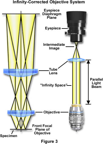
In modern infinity-corrected systems, the tube lens is a multi-element optic (to prevent introduction of coma or astigmatism even with increased "infinity light path space") built into and sealed in the observation tube. In this design, as many as two intermediate accessories can be accommodated, with no additional optics to correct the image, in the "infinity space" (see Figure 3) between the objective and the tube lens. Ghost images are eliminated as discussed above. Accessories are much easier to design; and unwanted extra magnification factors are avoided. The light paths illustrated in Figure 3 are diagrammatic representations of an infinity-corrected microscope system. The left-hand side of Figure 3 shows the focal points at the front focal plane of the objective and the eyepiece diaphragm plane. The right-hand side illustrates the "infinity space" between the objective and tube lens where intermediate attachments are placed into the light path.
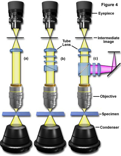
The schematic infinity-corrected systems illustrated in Figure 4 indicate how additional optical components can be inserted into the light path. Figure 4(a) is a diagrammatic representation of an infinity-corrected system showing a specimen on a microslide being illuminated by a substage condenser. The image-forming light rays pass through the objective and form a parallel light beam that is focused by the tube lens into the eyepiece. Accessories can be inserted into the parallel light beam without further optical correction as illustrated in Figure 4(b), which shows a Wollaston prism and several polarizers inserted into the pathway. Figure 4(c) illustrates the insertion of a beamsplitter into the parallel light beam. This beamsplitter diverts light to the external accessory positioned on the right of the parallel beam.
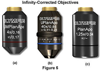
Infinity-corrected objectives come in a wide range of magnifications, from 1.5X to 200X, and in various qualities of chromatic and spherical correction—from simple achromats to planachromats and precision planapochromats. Most, but not all, are designed to be used dry, that is with air in the space between the objective and the specimen. The brightfield series have the customary microscope thread for screwing into the nosepiece (see Figure 5). The objectives which are used for brightfield/darkfield observation usually have wider diameter threads and require a nosepiece with wider openings for attaching such objectives (these objectives are called Neo, BF/DF, or B/D objectives).
Some reflected light objectives are designed to focus at a longer working distance from the specimen than is usual; such objectives are labeled on the barrel of the objective as LWD (long working distance) or ULWD (ultra-long working distance). The manufacturer usually designates the objective series to be used for reflected light Nomarski differential interference contrast studies; e.g., in the case of Olympus, the appropriate series is the MS Plan series for brightfield objectives and the Neo S Plan in the brightfield/darkfield series. Such objectives are sometimes labeled NIC on the objective barrel or designated as strain-reduced.
Infinity-corrected objectives are inscribed with an infinity mark (∞). The magnification yielded by the objective is the quotient of the focal length of the tube lens divided by the focal length of the objective. For example, in the Olympus microscope system with the tube lens having a focal length of 180 millimeters, a 9 millimeter focal length objective will project a 20X magnified image onto the plane of the eyepiece diaphragm. With a tube lens of 180 millimeters, it is possible to design objectives with a magnification as low as 1.25X while still maintaining the parfocalizing distance of 45 millimeters.