Anyone who has ever examined a coin in direct, bright light will have observed that the relief on the surface of the coin is very difficult to see under these illumination conditions, due to specular reflections from the surface of the coin. On the other hand, when incident light is arranged to "strike" the coin at a low glancing angle, the resulting shadow effect on one side and brightness on the other side (nearer the light) cause the relief detail of the coin to stand out in three-dimensional clarity.
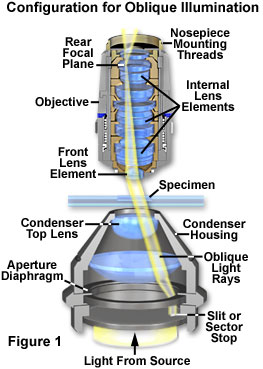
A somewhat similar appearance is produced when examining microscopic specimens with a classical technique known as oblique illumination (sometimes referred to as anaxial illumination). Direct light restricted to a single azimuth of the condenser light cone is allowed to illuminate the specimen from one side only, as illustrated in Figure 1. The net effect is to reveal details in pseudo-relief from an otherwise almost invisible, colorless specimen. A typical configuration for oblique illumination in compound transmitted light microscopy is presented in Figure 1. Beneath the condenser lens system is positioned an opaque light stop having a small slit (or sector stop), which is removed from the central optical axis of the microscope. Illuminating light rays from the source pass through the slit and subsequently through the condenser lens element system from a single azimuth that is off-axis. The oblique light rays then illuminate the specimen from a highly specific angle, on one side, and enter the microscope objective through the front lens element near the edge of the aperture (very close to the lens mount). The focused light rays converge at the objective rear focal plane and are directed to the microscope intermediate image plane, where they are observed through the eyepieces.
Oblique lighting has caused the zeroth order to be moved to a position just within the periphery of the objective aperture (this effect can be observed with an eyepiece telescope or Bertrand lens focused at the rear focal plane of the objective). The consequence of oblique illumination is to shift the zeroth order of light passing through the specimen from the center to one peripheral side of the objective front lens element. This shift of the zeroth order to a single side enables one or more additional higher orders of the diffracted light to be included at the rear focal plane of the objective and contribute to formation of the image. Only diffracted orders on a single side of the zeroth order (often termed sidebands) are admitted to the objective and, because of the obliquity of illumination, diffracted orders on the other side miss the objective altogether. This concept is illustrated in Figure 2 utilizing ray traces and a simple lens to represent the microscope objective.
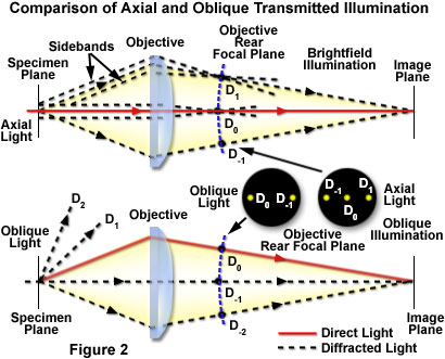
In general, when transparent specimens are illuminated in transmitted brightfield microscopy with a parallel bundle of light rays, the resulting images have poor visibility and lack any significant degree of contrast. This occurs because the sum of the light diffracted by each detail of the specimen is a quarter-wavelength out of phase with direct light passing through the specimen when both are recombined at the image plane. However, the diffracted light emanating from each specimen point contains sidebands (see Figure 2) on either side of the zeroth order undeviated light, which are offset from the quarter wave displacement by a defined margin. If one sideband of the diffracted light is prevented from reaching the image plane, constructive and destructive interference will occur between the remaining sideband and the direct light to produce a visible image at the intermediate image plane of the microscope. Oblique illumination is an excellent mechanism to achieve the sideband suppression necessary for the image formation process.
In Figure 2, the uppermost ray trace system identifies the pathway for axial light rays passing through the specimen and into the microscope optical system for a standard brightfield configuration. Symmetrical components of the diffracted light are admitted into the objective and produce complimentary patterns having no significant interference (either constructive or destructive) with the direct light components at the image plane, leading to images having poor contrast and visibility. With oblique illumination (the lower ray trace system in Figure 2), several of the diffracted component sidebands are not captured by the objective, but at least one higher order component is admitted along with the zeroth order (the second order sideband (D(-2)) is not included at the objective rear focal plane in the figure to increase the clarity of the illustration). Interference at the image plane produces an image of the specimen having significantly more contrast and visibility. The appearance of diffraction maxima at the objective rear focal plane for both axial and oblique illumination is also presented in the figure. Because only two maxima are necessary for image formation, oblique illumination will produce a visible image.
Oblique illumination is capable of resolving very fine specimen detail that is difficult to distinguish using conventional brightfield techniques. When oblique light rays strike the objective front lens at angle "ob" to the microscope optical axis, and the refractive index of the medium between the condenser front lens and the objective is n, the relationship between resolution, illuminating wavelength (λ), and refractive index can be described as:
Some authors equate the term n • sin (ob) with the numerical aperture of illumination, but this is misleading because the equation is not intended to signify a full cone of light emanating from all azimuths, but is restricted to a beam of light produced by anaxial illumination from a single azimuth. In cases where specimen detail is so fine that the zeroth order undiffracted and first order diffracted sideband light are separated by a distance equal to the diameter of the objective aperture, the resolving power is twice as high as observed for axial transmitted illumination and is expressed by the equation:
The optical conditions required for the microscope to conform with the equation above (when utilizing oblique illumination) are such that the fine details of specimen periodicity are limited by the resolving power of the objective. In many cases, specimen details that are resolved utilizing brightfield illumination are so severely lacking in contrast that they can scarcely be visualized or imaged. The net result of observing specimens with oblique illumination is often an increase in resolution (over that obtained in brightfield illumination with a closed condenser aperture diaphragm) and also the production of a shadowed, relief-like pseudo three-dimensional appearance in the image of the specimen.
Oblique Illumination Light Pathways
Examine how off-axis light rays can be collected by the microscope objective when illumination is shifted from axial (brightfield) to oblique (off-axis).
Start Tutorial »Oblique illumination techniques are ideal for imaging a wide variety of unstained objects such as living cells, crystals, diatoms, and similar transparent or semi-transparent specimens. However, the resulting images must be viewed and interpreted with caution because the diffracted orders from one side have not contributed to the image formation. Potential false structures appearing in the image can seriously limit the usefulness of oblique light to examine and quantitatively describe previously unobserved specimen detail. This fact should always be taken into consideration when observing specimens with oblique illumination.
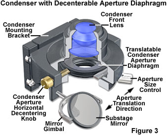
Achieving conditions necessary for oblique illumination, which has been employed to enhance specimen visibility since the dawn of microscopy, can be accomplished by a variety of techniques with a simple transmitted optical microscope. Perhaps the easiest methods are to offset a partially closed condenser iris diaphragm or the image of the light source. In former years, some microscopes were equipped with a condenser having a decenterable aperture iris diaphragm (illustrated in Figure 3; note that the lens system of the condenser should not be displaced from the center of the microscope optical axis). The device was engineered to allow the entire iris to move off-center in a horizontal plane so that closing the circular diaphragm opening would result in moving the zeroth order to the periphery of the objective rear focal plane. In advanced models, the entire diaphragm was rotatable around the axis of the microscope so that oblique light could be directed toward the specimen from any azimuth to achieve the best desired effect for a given specimen.
In practice, utilizing a partially closed condenser iris diaphragm technique to achieve oblique lighting is plagued with problems similar to those hampering brightfield observation. The results are a general loss of resolution and superimposition of diffraction rings, which surround and confuse the interpretation of minute specimen detail. In addition, Becke lines and other undesirable optical effects originating from regions of the specimen that are not in exact focus complicate the image. To circumvent many of these problems, a combination of oblique illumination at large condenser numerical aperture, coupled to video contrast enhancement, has been utilized as an effective method to generate optical thin sections that strongly resemble those observed with differential interference contrast (DIC) microscopy.
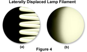
Although oblique illumination may be configured by decentering the condenser aperture, a majority of the condensers currently sold by the microscope manufacturers do not have this capability. An alternative technique involves lateral displacement of the tungsten lamp filament from the microscope optical axis, as illustrated in Figure 4. The diagram in Figure 4(a) presents the image of a focused filament, which has been translated to the right by adjustment of the lamp position in the lamphouse at the rear of the microscope. When a diffusion filter is inserted into the light path (Figure 4(b)), the light is spread to fill the condenser aperture with a gradient of illumination having the proper orientation for viewing specimens with the oblique method. Optimum gray tones can be achieved, in most cases, by placing the filament image in a position to cover approximately half of the condenser aperture diaphragm (as illustrated in Figure 4). However, careful adjustment of the filament position and condenser aperture, coupled to the utilization of diffusion screens having differing opacities, should allow the microscopist a significant degree of latitude in order to fine-tune modulation of image contrast.
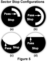
A more commonly employed alternative for establishing variable degrees of oblique illumination is the use of sector stops (Figure 5) placed just below the lower lens element and aperture diaphragm of the condenser. Many microscopes are equipped with a filter holder positioned near the bottom of the condenser, providing an ideal location for insertion of a sector stop. Illustrations of several sector stop designs are presented in Figure 5. In the past, sector stops were available from the microscope manufacturers, but they are increasingly difficult to find today. However, simple stops can be made from a section of opaque paper or cardboard and cut to fit the filter tray or taped to the underside of the condenser.
Each sector stop has a section that blocks light (labeled stop in Figure 5) and another area that allows only oblique light to pass through (labeled pass in Figure 5) and illuminate the specimen. The size of the stop and pass sections often vary with objective magnification and numerical aperture, and proper size determination is largely an experimental effort on the part of the microscopist to achieve the optimum balance. The sector stop can be rotated within the filter holder to illuminate the specimen from a variety of angles, or (more conveniently) a circular rotating stage can be employed to rotate the specimen through 360 degrees to achieve the desired oblique lighting effect. These suggestions can be employed as a guideline, but the individual microscopist should make final adjustments to both the condenser and sector stop configuration while observing the effects on the specimen image to optimize oblique illumination and enhance contrast and detail.
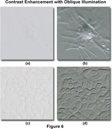
Oblique illumination can dramatically increase specimen contrast when compared to conventional brightfield techniques, as illustrated by the digital images presented in Figure 6. The specimen in Figure 6(a) is a bovine arterial cell that has been imaged using brightfield illumination with the condenser aperture adjusted for maximum contrast. It is obvious that the specimen is almost invisible and details are very difficult to distinguish in brightfield illumination. In contrast, when the specimen is illuminated obliquely using sector stops placed near the condenser aperture (Figure 6(b)), contrast is dramatically increased and many cellular details, including location of the nucleus and pseudopods, become visible. This particular specimen is difficult to image, regardless of the contrast enhancement technology employed by the microscopist (including phase contrast, differential interference contrast, darkfield, or Hoffman modulation contrast).
A somewhat easier specimen to image is the mouse kidney thick section presented in Figures 6(c) and 6(d). In brightfield illumination (Figure 6(c)), some specimen detail is visible, but specific features are difficult to distinguish and the overall image suffers from a serious lack of contrast. Utilizing sector stops to illuminate the specimen obliquely produces a significant improvement in contrast, as shown in Figure 6(d). In this digital image, minute specimen details become visible that were previously difficult to observe in brightfield illumination.
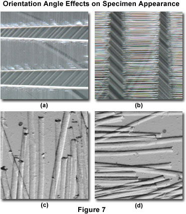
When compared to the darkfield technique, where the specimen is illuminated from all azimuths with highly oblique light, asymmetrical oblique illumination produces images whose character is highly dependent upon the incident angle of illumination. Images produced by oblique illumination are asymmetrical in the sense that edges lying perpendicular to the direction of incident illumination are made visible, while those that lie parallel (or close) to this direction are not. This concept is illustrated in Figure 7 for two specimens at different orientations with respect to the angle of incident oblique illumination. The specimen in Figures 7(a) and 7(b) consists of identical viewfields (but rotated by 90 degrees) obtained from a thin single-crystal wafer of lanthanum aluminate, a perovskite that is commonly employed as a substrate for epitaxial thin film deposition of high-temperature superconducting ceramics. Twinning in these crystals hampers confluent thin film formation and can have detrimental effects on the properties of resulting films. The digital image presented in Figure 7(a) depicts the pseudo-relief generated by twinning domains when the crystal is oriented with the longitudinal twin axis parallel to the oblique incident light rays. In contrast, when the crystal (and twin) axis is rotated by 90 degrees, so that it is perpendicular to the incident rays (Figure 7(b)), the twinning domains become readily apparent. This represents a spectacular display of specimen orientation restrictions on the textural effects observed under oblique illumination.
A similar, but less dramatic, result is obtained when observing semi-transparent goat hair specimens with oblique illumination at several orientation angles. When the long axis of the rod-like hair strands is oriented parallel to the incident oblique illumination (Figure 7(c)), structural details in the central portion and edges of the hair fibers is revealed. This detail is absent when the hair fibers are oriented perpendicular to the illumination axis (Figure 7(d)), and a significant difference is observed in the apparent thickness of the fibers between the two orientation angles. Fibers oriented parallel to the incident illumination appear to be much thicker than those oriented perpendicular to the light source. Thus, it is evident that the oblique illumination technique cannot be reliably employed to generate faithful measurement data from images gathered by this method.
The apparent three-dimensional effect afforded by oblique illumination techniques does not represent the actual specimen geometry or topography, and should not be employed to conduct measurements of specimen dimensions. The true value of the oblique illumination image is in revealing transitions in refractive index or other optical path differences within the specimen that enable the morphology and internal structural arrangement to be more clearly understood. The technique can be applied to a variety of materials that appear nearly invisible or transparent in brightfield illumination and cannot be stained or otherwise chemically or thermally treated to enhance contrast. Study of living organisms and processes such as in vitro fertilization, glass or acrylic fibers, chemical crystals, and other unstained materials can be facilitated by the utilization of an easily controlled oblique illumination system.
Refractive Index Determination by Oblique Illumination
Oblique illumination is sometimes utilized as an alternative to the Becke line test to determine whether the refractive index of a specimen is higher or lower than that of the surrounding medium. If the specimen is mounted in a medium of lower refractive index, shading that results from the anaxial illumination will appear on the side opposite to that from which the light enters the specimen, and vice versa, as illustrated in Figure 8. For both diagrams presented in Figure 8, two equal sized oblique light rays are depicted entering the specimen through the surrounding medium at the same angle of incidence. At point A on the left-hand diagram, the light is spread over a larger area of the specimen than at point B, so that the area near point A on the specimen appears darker than the area near point B. Under these conditions, one side of the specimen will appear shaded or somewhat darker than the other side when viewed through the microscope eyepieces (A' and B' in the upper left portion of Figure 8). This is the case when the specimen refractive index is higher than that of the surrounding medium.
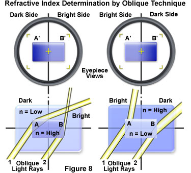
The opposite effect occurs when the specimen has a lower refractive index than that of the surrounding medium (right-hand side of Figure 8). In this case, the shaded or darker side of the specimen will be on the side that is nearest to the oblique light sector stop. When the specimen and the surrounding medium have identical refractive indices, then the specimen will be transparent (or invisible) and will have no refractive effects on the oblique illumination. The sensitivity of this refractive index determination technique is highly dependent on the condenser focal length, the iris diaphragm position, and the geometry of sector stops (if employed). In general, the best results are obtained when the condenser is carefully focused and an even field of illumination is achieved.
Oblique Illumination in Reflected Light
Reflected or incident light oblique illumination, although largely displaced by differential interference contrast and darkfield techniques, is often useful for examination of metals and other specimens in the field of metallurgy. A comparison between the basic configurations for transmitted and reflected light oblique illumination is presented in Figure 9. The diagram in Figure 9(a) illustrates the principal optical axes for axial (brightfield), oblique, and darkfield transmitted illumination. A simple lens simulates the microscope objective and yellow arrows represent hypothetical light rays oriented at the respective angles necessary to achieve the desired illumination mode. The angle θ refers to one-half the objective angular aperture. Light rays that are directed along the microscope optical axis are representative of axial illumination, while those lying between the axis and the limiting angle θ are captured by the objective front lens and form oblique illumination. Light rays having an incident oblique angle larger than θ do not enter the objective and represent darkfield illumination.
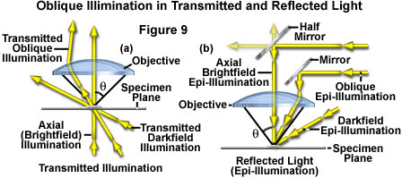
Principal light paths for reflected light or epi-illumination are presented in Figure 9(b). Axial (brightfield) epi-illumination proceeds in a direction parallel to the microscope optical axis from the vertical illuminator to the half mirror, where it is reflected through the objective lens system and onto the specimen. In contrast, oblique epi-illumination is reflected onto the specimen by a 45-degree prism or mirror mounted at the edge of the objective. These light rays pass through the periphery of the objective front lens element and strike the specimen obliquely, but are reflected, refracted, and diffracted back through the objective. As is the case in Figure 9(a), the value θ represents the one-half objective angular aperture through which all rays of axial and oblique illumination are directed. Light rays having a higher angle represent darkfield epi-illumination, which can originate from an external light source or an annular mirror or lens system that surrounds the objective. In Figure 9, only one imaging ray is illustrated for each illumination mode, but in reality, these light rays will propagate in all directions.
Oblique reflected or epi-illumination is suitable for the examination of periodic or linear structures on the surface of metals, ceramics, glasses, polymers, and other opaque specimens. For optimum results, the azimuth of illumination should be positioned at a 90-degree angle to the longitudinal direction of the structures under observation. The technique is very useful for examination of relief in surface structures (especially at lower magnifications), and can be utilized to demonstrate whether a structure on the surface of the specimen is a cavity or protrusion by determining the position of shadows relative to the illumination azimuth. In reflected oblique illumination, specimens should be examined through the complete range of inclination angles and azimuth directions available with the instrumentation to obtain the best possible analysis. If possible, a rotating circular stage should be employed, and the specimen rotated through a 360-degree angle to capture all essential surface detail. It should be noted that because oblique illumination can produce artifacts such as color fringes and directional contrast, the microscopist should compare oblique images to those obtained in brightfield illumination before attempting to interpret the results.
Advanced Oblique Illumination Techniques
Several microscopy techniques related to oblique illumination, including phase contrast and Hoffman modulation contrast, take advantage of fundamental optical parameters of the microscope. Specifically, these methods are based on the fact that the condenser and objective lens apertures are in principal conjugate planes and that the illuminating beam arising from each point of the condenser aperture is diffracted at a different angle (according to its spatial frequency) by the specimen. Another basic concept, utilized by these techniques, is the fact that the objective rear aperture is the Fourier optical plane of the microscope.
In Hoffman modulation contrast microscopy, a sophisticated derivative of the oblique illumination technique, the condenser aperture is fitted with a slit mask having the slit positioned near the edge of the aperture. The objective rear focal plane contains a second, complementary mask, termed a modulator, which consists of three zones having differing degrees of transmittance. Oblique illumination passing through the condenser slit is projected onto the central zone of the modulator and forms an image of the slit in this zone. The central zone has an optical density allowing only 15 percent of the light entering the zone to be transmitted through the modulator, while a darker (but smaller) zone transmits only 1 percent of the light. The largest area of the modulator plate comprises the third zone, which is transparent, and passes essentially all of the incident light (minus that lost due to reflection and absorption). The objective modulator plate (mask) thus attenuates the zeroth-order light undiffracted by the specimen (that passing through the zone of 15 percent transmission) while the light diffracted toward the dark sector (1 percent transmission) is blocked. The light diffracted by the specimen away from the dark sector of the mask passes unchanged, resulting in a shadow-cast image similar in appearance to that produced by differential interference contrast, which enhances gradients of refractive indices or of optical path differences in the specimen.
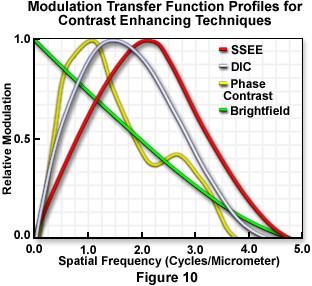
A related technique, known as single-sideband edge enhancement or SSEE utilizes an adjustable half-stop in the condenser front focal plane to occlude a portion of the condenser aperture. A complementary spatial filter located in the objective conjugate rear focal plane attenuates and controls the phase shift of the undiffracted light beam transmitted through the microscope. The degree of attenuation and the phase shift of the background (direct) wave, relative to light scattered and diffracted by the specimen into the aperture region obscured by the half-stop, are adjustable. Images generated by this technique are again similar in appearance to those obtained by differential interference methods, but the single-sideband approach, unlike DIC, does not require polarization optical elements to sandwich the specimen. The system can be adjusted to detect extremely minute phase differences in specimens, as well as anisotropies of refractive indices at high resolution. The technique takes advantage of the fact that only one of the two diffraction sidebands must be captured in order to gain the information regarding the spatial frequency in the specimen that gives rise to that particular diffraction angle. As presented in Figure 10, single-sideband edge enhancement contrast provides a high-spatial-frequency modulation transfer function superior to that provided by other popular modes of contrast generation.
Conclusions
The optical effects that occur when a microscope objective is illuminated at its margin vary considerably according to lens quality, correction for aberration, and the specimen characteristics. When the illumination beam falls partially outside the objective aperture, as it does in oblique illumination, the result is a reduction of zeroth order light intensity relative to the sideband intensity, and a diffraction pattern is generated at the edge of the objective aperture. For this reason, the illuminating cone should be restricted to less than the full objective aperture to avoid diffraction artifacts (such as interference fringes). Careful experimentation with condenser illumination methodology should ensure an even illumination field at restricted apertures.
There are several advantages to oblique illumination when compared to differential interference contrast and phase contrast. Birefringence inherent in a specimen does not confuse oblique illumination images, as is the case with DIC, but phase details are clearly observed in directionally shadowed images from the oblique illumination. A good example is vertebrate axons, which are more clearly imaged with oblique illumination due to their highly birefringent myelin sheaths that create excessive contrast in DIC. In addition, equipment costs are significantly less for oblique illumination than with either DIC, phase contrast, or Hoffman modulated contrast, because the only requirement is a properly configured brightfield microscope. In some cases, oblique illumination techniques enable the microscopist to image deeper into tissue layers than is possible with DIC. Finally, resolution is not compromised over that attainable with brightfield, and contrast can be dramatically enhanced.