Photography through the microscope is complicated by a wide spectrum of unexpected color shifts and changes that affect how the image is rendered on the film emulsion or digital electronic image capturing device. These unexpected imaging results are caused by a number of factors ranging from incorrect color balance between the light source and the film emulsion to optical artifacts such as aberration and lamp voltage fluctuations.
If color temperature differences between the film emulsion and microscope light source have been carefully controlled, as described in our discussion on color temperature, then minor adjustments to the color balance of the microscope light source can often alleviate color shift problems. In most cases, the reason for undesirable color effects is very clear or can be easily determined by careful examination of the conditions under which the exposure was made. In other cases, the problem is not immediately obvious and may require a detailed investigation before the cause is uncovered.
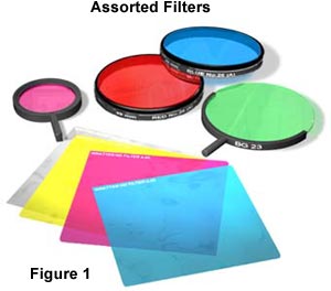
After the basis of a color photomicrography problem has been determined, it is usually very easy to correct with the appropriate use of filters of one type or another. Filters are used to selectively block or decrease the intensity of selected wavelengths while transmitting all other portions. A variety of filters are commercially available to assist the photomicrographer in compensating for optical and illumination problems in order to obtain the highest quality images possible. Many photomicrography color shifts or casts can be cured by inserting the appropriate Kodak Wratten Color Compensating filter into the optical pathway. Other filters such as neutral density, contrast enhancement, ultraviolet absorption, heat absorption, infrared, and filters designed to assist in bringing out details of biological stains are also commonly used. These filters are discussed in detail below.
Exposure and Color Balance
Explore how exposure settings and color compensating filters can be adjusted to change the contrast, brightness, and color balance of a photomicrograph.
Filters are commonly available in the form of glass, plastic-coated glass, acetate, or gelatin bases that have been coated, mixed, or impregnated with organic and inorganic dyes obtained from both natural and synthetic sources. The quality of glass or polymer used in the manufacture of filters is important, and should be of optical grade and provide uniformity of density and color over the entire microscope viewfield. Gelatin filters are the most cost effective and optically satisfactory filters available commercially, making this the filter material of choice for critical photomicrography, despite the gentle handling required. Optical glass filters are also excellent, but these are not available to meet all of the needs for microscopy. Acetate filters are generally used in nonimage-forming systems where the need for quality and precision is unimportant. Typically, acetate filters are used in photographic enlargers and printers. Plastic-coated filters are used primarily for safelight applications in the darkroom and are not appropriate for optical microscopy. The terminology used by various manufacturers can be confusing, because filters are often referred to by product number or by some aspect of their filtration properties. There are very few industry-wide standards for filter nomenclature.
Color Compensating Filters - Kodak manufactures the Wratten series of color compensating filters designed for a wide spectrum of laboratory and industrial applications. These filters consist of colloidal carbon mixed with suitable dyes and dispersed in gelatin to achieve the desired spectral characteristics. Color compensating filters differ from color balance and conversion filters in that they control color by attenuating principally the red, green, and/or blue regions of the visible light spectrum. They are abbreviated with the prefix CC, for Color Compensating, followed by the filter nominal peak density ranging from about 0.025 to 0.5 multiplied by 100, and ending with the capitalized first letter of the filter color (for example M for magenta). Thus, the abbreviation for a yellow color compensating filter having a nominal peak density of 0.3 would be: CC30Y.
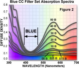
Each filter in this series controls the amount of a single color while passing one or both of the remaining two colors. In this manner, color compensating filters can make subtle changes to the color balance of the light source, or they can compensate for deficiencies in the spectral output. The visible absorption spectra for a series of blue color compensating filters (CC025B through CC50B) is illustrated in Figure 2. Principal minima appear in the range 380-490 nanometers for all filters in this series, which pass most blue wavelengths and filter green, yellow and red wavelengths when placed into the optical path of a microscope.
Color compensating filters are labeled with a number (nominal peak density) to indicate their ability to absorb light. The most commonly used densities are 05, 10, 20, 30, 40, and 50, which increase filter optical density incrementally from lesser (05) to greater (50) densities. As an example, a number 30 filter reduces the level of its complementary color by 50 percent, or one exposure step. A CC30M filter (magenta) absorbs 50 percent of the green light passing through it. Color compensating filters can be used in combination (for example, CC20Y (yellow) + CC20M (magenta) = CC20R (red)), but in order to obtain the best results, only a single filter should be used. When two filters are combined, a slightly different color is created, an artifact that can obscure color deficiencies in a photomicrograph.
One of the primary uses for color compensating filters is to overcome variations in film emulsions from within a batch or between different batches. Manufacturing of color film is a complex process that involves coating a polymer base with numerous light-sensitive emulsions that are only a few microns thick. Fluctuations in emulsion thickness will affect the color balance and may show up in one or more individual photomicrographs, on an entire roll of film, or in part of a batch. Manufacturers permit a fluctuation tolerance equivalent to the effect of a CC10 filter, a variation that has been demonstrated to be acceptable to most users.
Critical photomicrography dictates that color compensating filters be used for careful control of color shifts, which may vary in any one of the six primary colors: red, green, blue, cyan, magenta, and yellow. Most often, film batch variations are first apparent when observing the background colors on new photomicrographs. This color should be a neutral light gray or white, and color shifts are usually very obvious when they occur. It is a simple matter to correct the color balance with color compensating filters by using a filter complementary to the color shift present in the background. When undertaking a heavy photomicrography load using color film, it is wise to purchase film that has the same emulsion number on each roll and store the excess in a refrigerator or freezer. A test roll can then be used to determine color compensation and balance variables that should remain constant for the rest of the film batch. The recommended procedure is to expose a single frame with no compensation filter, followed by frames exposed through each of the CC10 series filters (CC10R, CC10G, CC10B, CC10C, CC10M, and CC10Y). After aligning all seven photomicrographs on a 5000 K light table, the background that displays a clean white or very light gray background is the one that has been filtered correctly.
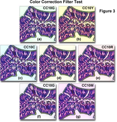
The photomicrographs illustrated in Figure 3 demonstrate a color correction filter test using a photomicrograph of a eosin/hematoxylin stained thin section of human lower duodenum tissue. Figure 3(d) shows the baseline color balance with no color correction filters added. The overall yellow cast to the image suggests that a CC10G filter (Figure 3(f)) is the proper filter for color correction. In fact, the background in Figure 3(f) is the cleanest and purest of all the images in Figure 3, and represents the best choice for color correction. Other filters (Figure 3(a,c,e,f,g)) produce backgrounds in the photomicrograph reminiscent of the compensating filter colors. Placing a CC10Y filter in the light path (Figure 3(b)) only increases the intensity of the yellow background.
In many instances, low density color compensating filters can be effectively used to enhance color rendition in tissue thin sections that are stained with various dyes. Each specimen must be evaluated on a trial and error basis, because overuse of color compensating filters can lead to degradation of complementary stain colors and may render the background with a tint. It is generally advisable to restrict color compensating filters to densities below CC20 when attempting to use them to enhance stain colors.
As suggested by John G. Delly, there are cheaper alternatives to Kodak Wratten filters for a microscopist on a budget, or when these filters are not available. Kodak also manufacturers a Color Print Viewing Filter Kit that contains a set of transparent filters having density values of 0.10, 0.20, and 0.40 for each of the six colors (red, green, blue, cyan, magenta, yellow). These filters can be placed on the microscope light port to provide a quick and easy color correction. Although not manufactured to the same critical tolerances as the Wratten or color printing filters, the viewing filters can often be substituted if they do not have serious blemishes on the surface. Kodak also offers a set of acetate color printing filters (Color Printing Filter Set), which is available in 75 × 75 millimeter squares and contains enough filters to match most densities provided by the Wratten filters.
Use the link below to navigate to pages containing data for individual color compensating filter specifications:
- Color Compensating Filter Data - Visible absorption spectra and tables containing the wavelengths of principal maxima are provided for the Kodak Wratten series Color Compensating Filter family.
Neutral Density Filters - In situations where the microscope illumination appears too bright for comfortable observation and photomicrography, the light intensity should be reduced by use of neutral density filters, often termed ND filters. These filters are neutral gray in color and designed to reduce transmitted light intensity evenly across a portion or the entire wavelength spectrum without introducing a significant change in color temperature. Neutral density filters are ideal for controlling color photomicrograph exposure times without adjustments to the lamp voltage. Their principal use in optical microscopy is to lengthen exposure times in situations where lamp intensity is so great that the shortest exposure allowed by the photomicrographic equipment exceeds the time necessary to capture the image correctly.
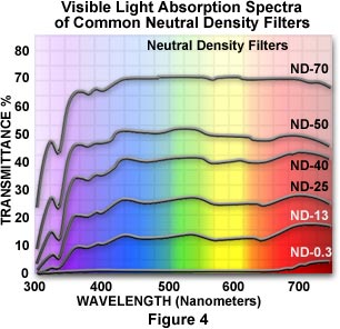
There are two classes of neutral density filters: absorptive and reflective, which work by absorbing or reflecting a selected band of wavelengths. Illustrated in Figure 4 are the visible light absorption spectra for a series of common neutral density filters. As can been seen in the figure, these filters display a relatively constant extinction coefficient throughout the visible (400 to 700 nanometers) light range. Each neutral density filter increment from ND-0.3 to ND-70 in Figure 4 has a successively larger extinction coefficient, which collectively provide a uniform series of filters for adjusting illumination.
Neutral density filters are manufactured using gelatin, polymeric, or glass substrates that have impregnated or dissolved materials to reduce optical transparency. Kodak Wratten Neutral Density filters are very popular, and are made with the proprietary gelatin thin films. A colloidal carbon suspension containing a selected complement of organic dyes is mixed with liquid gelatin until the desired neutral density is achieved. This combination is then coated onto a supportive glass substrate until it forms a very thin film of uniform thickness. After drying, the film is stripped from the substrate and coated with lacquer for protection. Note that even though neutral density, color compensating, and other Wratten filters are protected by a lacquer overcoat, they are still suseptible to damage (particularly from scratches), and should be handled only at the edges or in the corners. An alternative is to protect gelatin Wratten filters by placing them in a simple metal frame, also marketed by Kodak. Never expose the filters to temperatures exceeding 50 degrees centigrade for extended periods. It is also important that these filters not be placed too close to the tungsten-halogen light source of the microscope to avoid damage due to the heat generated by the lamp.
Specifications for the most commonly used neutral density filters are listed in Table 1. Each neutral density filter is designated by an alphanumeric code, ND-XX, where XX is the average transmitted light percentage by the filter. Thus, an ND-60 filter transmits (or passes) 60 percent of the incident light from the light source and a ND-0.1 filter transmits 0.1 percent of incident light. The optical density of a neutral density filter is defined as the logarithm (base 10) of the absorbance (reciprocal of transmittance) according to the equation:
Where:
And, therefore:
Where T is the percent of light being transmitted through the filter, D is the optical density, and A is the absorbance. Most microscopists refer to the density rather than the opacity (reciprocal transmittance) when working with neutral density filters. This is probably more appropriate because the human eye perceives light intensity differences on a logarithmic scale.
Neutral density filters can be stacked together to achieve density values for which there is no filter. Stacking these filters is additive, so that placing a ND-50 (density = 0.3) and and ND-60 (density = 0.2) filter into the light path is equivalent to such placement of a ND-30 (density = 0.5) filter. A filter with a density of 0.30 has a transmittance of 50 percent (ND-50, Table 1), so it can be used to reduce the microscope lamp intensity by a factor of two. Likewise, a filter having a density of 0.6 (ND-25, Table 1) has a transmittance value of 25 percent (reduces lamp intensity by a factor of four), and a filter of density 1.0 (ND-2.0, Table 1) can reduce lamp intensity by a factor of 10 (transmittance value of 10 percent).
As mentioned previously, adjustment of exposure in photomicrography is one of the primary purposes for using neutral density filters. Many modern microscopes have exposure monitors with LCD screen displays that inform the operator of the exposure time at shutter speeds up to hundredths of a second. These monitors also usually allow for exposure adjustment in 1/3 to 1/2 f-stop increments. In some instances, especially when using brightfield illumination with high-energy tungsten-halogen lamps, exposure times recommended by the monitor are less than 0.05 seconds. This is a very short time, which can lead to inadequate exposure and vignetting of the image. Adding a ND-50 neutral density filter to the light path will double the necessary exposure time to 0.1 seconds, while a ND-25 filter will increase the exposure to a comfortable 0.2 seconds.
Neutral Density Filter Specifications
| Designation | Density | Transmission (Percentage) |
|---|---|---|
| ND-80 | 0.1 | 80 % |
| ND-70 | 0.15 | 70 % |
| ND-60 | 0.2 | 60 % |
| ND-50 | 0.3 | 50 % |
| ND-40 | 0.4 | 40 % |
| ND-30 | 0.5 | 30 % |
| ND-25 | 0.6 | 25 % |
| ND-20 | 0.7 | 20 % |
| ND-16 | 0.8 | 16 % |
| ND-13 | 0.9 | 13 % |
| ND-10 | 1.0 | 10 % |
| ND-1 | 2.0 | 1 % |
| ND-0.1 | 3.0 | 0.1 % |
| ND-0.01 | 4.0 | 0.01 % |
Table 1
The ability to adjust exposure with neutral density filters is especially important for cameras that have fixed shutter speeds (these speeds range from about 1/500 second to a couple of seconds), in which each sequential speed increases exposure by a twofold increment. For instance, an exposure meter might recommend a shutter speed of 1/1000 second for a shutter that has a maximum speed limited to 1/250 second. By placing a ND-25 neutral density filter in the light path, the lamp intensity is effectively reduced by a factor of four, increasing the recommended exposure time to 1/250 second. To achieve a more comfortable shutter speed, use a ND-2.0 filter to boost the exposure time to 0.1 seconds.
Neutral density filters are also useful for exposures that lie between two shutter speeds. In a situation where a shutter speed of 1/125 second is too short, but 1/60 second is too long, neutral density filters can be placed in the light path to adjust illumination to accommodate an exposure in between these two values. A ND-60, ND-70, or ND-80 filter used with the 1/125 second shutter speed will add 1/3 to 2/3 of an f-stop to the exposure time, allowing more latitude in exposure. The actual exposure must be determined by trial and error, but neutral density filters should be routinely used to adjust exposure time on fixed shutter speed cameras. Be careful not to introduce very long exposures through the use of neutral density filters, because this can lead to reciprocity failure and associated color balance artifacts.
Older neutral density filters may acquire a slight yellowish tinge with age, and some of the cheaper filters also have some degree of background color. If the introduction of neutral density filters into the optical pathway results in incorrect color balance for a microscope that has been carefully calibrated, use color compensating filters to return the microscope light source to its proper balance. Other optical factors, such as internal scattering and reflections, can affect the effective density of neutral density filters, causing them to vary from the measured density. For this reason, it is important to calibrate neutral density filters for critical photomicrography.
Filters for Stained Specimens - Thin sections of biological tissue are often stained with one or more organic dyes to selectively enhance visibility of various features present in the specimen. The intensities and hues generated by most biological tissue stains will reproduce very well on color film, but some stains tend to appear washed out or have their colors shifted, especially in multiple stain mixtures. In many instances, color compensating filters can help restore most or all of the lost color, but too much filtration can affect the color of neighboring stained features and the background. This problem occurs with the popular stains eosin, fuchsin, and methylene blue, which are not reproduced very well on most color films. Often, tissues stained with these dyes, either singly or in mixtures, appear muddy and lacking in color saturation.
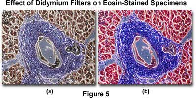
To counteract this effect, microscopists employ a didymium filter, which contains a combination of rare earth elements dissolved in glass. Didymium filters remove a portion of the orange region of the visible light spectrum, an effect that increases the color saturation intensity of brown, blue, and red-stained features in the specimen. The extinction coefficient is highest between 580 and 590 nanometers for the didymium filter, allowing the filter to remove most of the orange and yellow colors that tend to dull red and blue tones in stained thin sections.
Didymium Filters
Examine the effects a didymium filter has on color rendition of specimens stained with eosin, fuchsin, and methylene blue.
Illustrated in Figure 5 are two photomicrographs of the same specimen, a thin section of human pancreas stained with a mixture of eosin and hematoxylin. The photomicrograph on the left (Figure 5(a)) was taken without the benefit of color compensation filters or a didymium filter. On the right (Figure 5(b)) is an image of the same viewfield, this time with a didymium filter inserted into the light path. Note the dramatic increase in color saturation for red and blue color tones in this photomicrograph.
Didymium filters are produced in very thin glass sections with a thickness of between one and two millimeters, because the amount of light absorbed by the filter is dependent upon filter thickness. Thicker didymium filters can introduce artifacts such as colored backgrounds and degradation of other stain colors. Most major microscope manufacturer offer a didymium filter of proper dimensions as an optional accessory.
In some instances, the background of a biological specimen can become lightly colored during the staining procedure, an undesirable artifact. To avoid this, color compensating filters can be used to subtract the background color, provided it is not too saturated. Another problem with stained thin sections is coloration of the mounting medium. Canada balsam, a popular medium for preparing thin sections, will usually turn light yellow with age or in whole mount specimens. A blue color compensating filter (CC10-20B) will usually overcome this problem, unless the specimen is a very thick whole mount. In this case it may be impossible to completely neutralize the yellow tint.
Ultraviolet Filters - Tungsten microscope lamps do not emit a significant amount of ultraviolet light, but some of the newer tungsten-halogen lamps in addition to mercury and xenon lamps produce a considerable amount of ultraviolet light in the 300-400 nanometer range. Ultraviolet radiation can expose the blue-sensitive emulsion layer in many color films, causing the overall photomicrograph to have a blue cast. This is primarily a problem with fluorescence microscopy, but it can occur in any microscope using a high intensity tungsten-halogen, mercury, or xenon lamp. To reduce ultraviolet light, use the Kodak Wratten 2B or 2E filters that absorb ultraviolet radiation below 390 and 415 nanometers, respectively. The 2B filter will remove essentially all ultraviolet wavelengths, leaving only visible light to illuminate the specimen. Having a larger spectrum of blocked wavelengths, the 2E filter also will remove some of the violet and shorter wavelength blue light, so this filter is less desirable for color photomicrography.
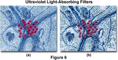
The effects of ultraviolet light on color photomicrography are illustrated in Figure 6. The image on the left (Figure 6(a)) shows a eosin-hematoxylin stained thin section of mucus-secreting tubular glands in the epithelium of the human colon. There is an overall blue cast to the photomicrograph that pervades most specimen features and the background. After placing a Kodak Wratten 2B filter into the microscope light path, the image on the right (Figure 6(b)) was obtained. Note that this photomicrograph demonstrates better color saturation and a cleaner background with elimination of the blue cast.
Flash tubes may also produce a considerable amount of ultraviolet light, and might require the use of a filter to remove unwanted wavelengths. Many modern transparency films color balanced for daylight illumination contain a ultraviolet absorbing mask as one of the film layers. In this case, use of filters is probably not necessary. It is a good idea to read the manufacturer's specification sheet on each new film type to ascertain whether it is protected by an ultraviolet light blocking layer.
Heat-Absorbing Filters - Almost 90 percent of the radiation emitted by a tungsten or tungsten-halogen lamp occurs in the form of infrared wavelengths, which is associated with the production of heat. Mercury and xenon arc lamps also produce a considerable amount of heat. Heat-absorbing filters can be added to the microscope light path, near the illuminator, to remove unwanted infrared wavelengths and protect microscope optical components, filters, and the specimen from heat damage. In fact, most major microscope manufactures offer heat-absorbing filters as standard equipment, and some even incorporate these filters into the illuminator. If you suspect that your microscope illuminator may have a built-in heat-absorbing filter, consult the owner's manual or contact your instrument dealer. Many OEM illuminator heat filters cannot be easily removed and should be left in place.
Some heat-absorbing filters are made from a special type of Pyrex glass known as Aklo, which absorbs infrared heat rays, and is green or blue-green in color. Filters made with Aklo may introduce color balance deviations into photomicrographs. This side effect can be corrected with color compensating filters that are complementary to the heat-absorbing filter color. If the heat filter can be removed from the lamp housing, do so and examine it on a 5500 K light table. Light green heat filters can be compensated by a CC10M or CC20M magenta color compensating filter, and blue-green heat filters can be compensated by a light red (CC10R or CC20R) filter. Place the complementary filters on top of the heat filter until one is found that exactly balances the tinge on the heat filter and turns the color to neutral. When inserted into the microscope light path, this compensating filter should alleviate color balance problems. Some of the newer microscopes have dichroic interference filters designed to reflect heat back into the lamphouse. Dichroic filters are far more efficient at blocking heat than quartz or glass heat-absorbing filters, and will not crack or break when a significant amount of heat is absorbed.
In order to exploit the full potential of filters in color photomicrography, the microscopist must have a complete understanding of the technical aspects of the interaction between filters, visible light, and film emulsions. When filters are applied correctly to solve color shift and balance problems, the quality of color photomicrographs is greatly improved.
