Acousto-Optic Tunable Filters (AOTFs)
The integration of optoelectronic technology into confocal microscopy has provided a significant enhancement in the versatility of spectral control for a wide variety of fluorescence investigations. The acousto-optic tunable filter (AOTF) is an electro-optical device that functions as an electronically tunable excitation filter to simultaneously modulate the intensity and wavelength of multiple laser lines from one or more sources. Devices of this type rely on a specialized birefringent crystal whose optical properties vary upon interaction with an acoustic wave. Changes in the acoustic frequency alter the diffraction properties of the crystal, enabling very rapid wavelength tuning, limited only by the acoustic transit time across the crystal.
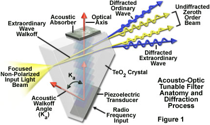
An acousto-optic tunable filter designed for microscopy typically consists of a tellurium dioxide or quartz anisotropic crystal to which a piezoelectric transducer is bonded. In response to the application of an oscillating radio frequency (RF) electrical signal, the transducer generates a high-frequency vibrational (acoustic) wave that propagates into the crystal. The alternating ultrasonic acoustic wave induces a periodic redistribution of the refractive index through the crystal that acts as a transmission diffraction grating or Bragg diffracter to deviate a portion of incident laser light into a first-order beam, which is utilized in the microscope (or two first-order beams when the incident light is non-polarized; see Figure 1). Changing the frequency of the transducer signal applied to the crystal alters the period of the refractive index variation, and therefore, the wavelength of light that is diffracted. The relative intensity of the diffracted beam is determined by the amplitude (power) of the signal applied to the crystal.
In the traditional fluorescence microscope configuration, including many confocal systems, spectral filtering of both excitation and emission light is accomplished utilizing thin-film interference filters. These filters are limiting in several respects. Because each filter has a fixed central wavelength and passband, several filters must be utilized to provide monochromatic illumination for multispectral imaging, as well as to attenuate the beam for intensity control, and the filters are often mechanically interchanged by a rotating turret mechanism. Interference filter turrets and wheels have the disadvantages of limited wavelength selection, vibration, relatively slow switching speed, and potential image shift. They are also susceptible to damage and deterioration caused by exposure to heat, humidity, and intense illumination, which changes their spectral characteristics over time. In addition, the utilization of filter wheels for illumination wavelength selection has become progressively more complex and expensive as the number of lasers being employed has increased with current applications.
Rotation of filter wheels and optical block turrets introduces mechanical vibrations into the imaging and illumination system, which consequently requires a time delay for damping of perhaps 50 milliseconds, even if the filter transition itself can be accomplished more quickly. Typical filter change times are considerably slower in practice, however, and range on the order of 0.1 to 0.5 second. Mechanical imprecision in the rotating mechanism can introduce registration errors when sequentially acquired multicolor images are processed. Furthermore, the fixed spectral characteristics of interference filters do not allow optimization for different fluorophore combinations, nor for adaptation to new fluorescent dyes, limiting the versatility of both the excitation and detection functions of the microscope. Introduction of the acousto-optic tunable filter to confocal systems overcomes most of the filter wheel disadvantages by enabling rapid simultaneous electronic tuning and intensity control of multiple laser lines from several lasers.
Underlying Principles of AOTF Operation
An acousto-optic crystal is defined as having optical properties that are altered in the presence of an acoustic wave. When an acoustic wave propagates through such a material, the crystal lattice structure is alternately compressed and relaxed in response to the oscillating wavefront. The basic mechanism responsible for this acousto-optic interaction is known as the elasto-optic effect. Periodic regions of lattice compression and rarefaction throughout the crystal are manifested as refractive index fluctuations that can produce diffraction of incident light. Although the function of the acousto-optic tunable filter is similar to that of a diffraction grating, its behavior differs in that diffraction occurs over an extended volume of the crystal rather than at a planar surface, and only a limited band of spectral frequencies are affected. In this respect the AOTF performs more as a bandpass filter than a diffraction grating. The propagating acoustic waves generate a periodic modulation of the index of refraction throughout the crystal, effectively producing a mobile phase grating, which will diffract portions of the incident light that satisfy appropriate phase-matching (or momentum-matching) conditions. For a particular acoustic frequency, only a limited range (band) of spectral frequencies satisfies the phase-matching condition, and becomes diffracted. Varying the radio frequency driving the piezoelectric transducer changes the center of the spectral passband, as required to maintain the phase-matching condition. Appropriate selection of the drive frequency allows the crystal to be tuned to separate a particular wavelength band for diffraction, which then exits the crystal at a distinct angle relative to the undiffracted beam.
The diffracted wavelength(s) vary as a function of the radio frequency signal applied to the crystal. For a specific set of AOTF design parameters (including crystalline material and geometry), the central wavelength (λ) of the passband is determined by the phase-matching (and momentum-matching) condition defined by the following equation:
λcenter = V • Δn/f
In the preceeding equation, V is the acoustic wave velocity, Δn is the birefringence of the acousto-optic crystal, and f is the acoustic wave frequency. The amplitude of light waves transmitted in the diffracted beam is proportional to the radio frequency power applied to the crystal. Consequently, varying the frequency and power of the RF signal provides a mechanism for selecting the wavelength and intensity of the light filtered by the AOTF.
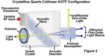
The initial AOTF design centered on a configuration in which the interacting acoustic and optical waves are collinear, as illustrated in Figure 2. In this design, the acoustic wave is launched along a principal axis of the crystal, and the incident optical beam passes through a polarizer and follows the same propagation path along the crystal axis, interacting collinearly with the acoustic waves (Figure 2). A narrow band of spectral wavelengths is diffracted into a polarization direction orthogonal to that of the incident beam, and can be separated from the coupled collinear beams by an output polarizer (Analyzer Beamsplitter, Figure 2). As described previously, the center of the wavelength passband is determined by the phase-matching condition that exists between optical and RF signal frequencies.
The collinear AOTF geometry is restricted to use with a limited category of crystals, which unfortunately does not include some of the most efficient acousto-optic materials. In order to take advantage of the benefits from materials such as tellurium dioxide, and to utilize a geometry that is simpler to fabricate, a configuration in which the acoustic and optical waves are noncollinear was developed (Figure 1). In this design, the narrowband diffracted light and incident broadband light is physically separated, and because they exit the crystal through different pathways, polarizers are not required for operation. The zeroth-order undiffracted beam can be blocked by a beam stop, while the filtered diffracted beam is utilized for specimen illumination. A phenomenon referred to as acoustic walk-off is illustrated in Figure 1 by the angular difference between the acoustic group velocity and the normal to the acoustic wavefront, a variance that is common to many acousto-optical devices. The significance in a collinear AOTF configuration (Figure 2) is that although the direction of light propagation and the acoustic phase velocity are by definition collinear, the resulting acoustic group velocity follows a slightly different angle.
When a non-polarized incident light beam is employed in the noncollinear configuration (illustrated as a focused light cone in Figure 1), the diffracted portion of the beam comprises two spatially separated first-order beams, which are orthogonally polarized. If the input beam to the AOTF is linearly polarized (as with a laser source), only one diffracted beam exits the device, with its polarization state rotated 90 degrees relative to the input polarization axis. Because the two orthogonally polarized first-order beams do not separate until they leave the crystal, and then diverge at a fixed angle, the diffraction angle (and spatial location of the resulting image) does not change with wavelength. In applications that utilize the noncollinear AOTF as a tunable filter, the first-order diffracted component is allowed to illuminate the specimen (typically only one diffracted output is used), while the zeroth-order beam is blocked. The two beams are typically separated by a few degrees, which is a function of the device design. By utilizing crystals having larger birefringence values, this deflection angle (the angle separating the diffracted and undiffracted beams) is increased, a desirable property for achieving adequate separation between the diffracted and undiffracted beams without using polarizers. The deflection angle taken by the diffracted beam is at a minimum for the tellurium dioxide crystal system when the beam incidence angle is parallel to the [110] axis (at 90 degrees to the optical axis), and increases up to a practical limit between 8 and 9 degrees as the incidence angle increases with respect to the [110] axis. The deflection angle occurring between the diffracted and undiffracted beams after leaving the crystal has the following relationship to the birefringence of the crystal material:
θi - θd = Δn sin 2θi
In the expression above, θ(i) and θ(d) are the angles, relative to the optic axis, of the incident and diffracted beams, respectively. The birefringence is represented by Δn. AOTF devices based on the collinear mode of operation, such as those utilizing quartz as the birefringent material, can be considered a simplified variation of the noncollinear design with an incidence angle, θ(i), of 90 degrees, and a deflection angle of zero.
Although in principle, both isotropic and anisotropic Bragg diffraction patterns can be exploited as mechanisms for spectral filtering, a critical limitation exists in the use of isotropic filter media, because the spectral passband varies with the incident light angular aperture, and therefore a well-collimated beam is essential. The effect of angular aperture on passband properties results from the fact that changes in the incidence angle produce momentum mismatches, causing the diffracted beam to be deflected differently for each wavelength. For a divergent incident beam, the optical passband width is dramatically increased compared to that for a collimated beam, severely limiting the practical angular aperture of the filter.
The anisotropic acousto-optic filter has the practical advantage that a narrow passband can be maintained over a large range of incident beam angles. With this design, the polarization plane of the diffracted beam is rotated 90 degrees relative to the undiffracted beam polarization direction. Because the refractive indices experienced by the ordinary and extraordinary rays in a birefringent crystal are unequal, the acoustic wave propagation direction can be chosen to cause the group velocity for the incident and diffracted light to be collinear (a condition referred to as noncritical phase matching). In this situation, the momentum mismatch produced by the angular variation of the incident light beam is maximally offset by the angular change due to birefringence. Since the noncritical phase matching condition is satisfied over a large range of incident beam angles, the angular field of view for a noncollinear AOTF can be relatively high, while maintaining desirable properties, such as a narrow passband.
Materials for AOTF Fabrication
The significant increase in the number of applications utilizing acousto-optic devices in recent years has largely occurred due to the development of improved materials for their fabrication. The selection of an appropriate material depends on the specific device target function. For example, gallium phosphide has superior characteristics for construction of wideband acousto-optic deflectors and modulators, but because the crystalline structure is optically isotropic, the material is not suitable for tunable filter devices. Specific general requirements, however, pertain to any type of optical device, and these include high optical transparency over the wavelength range to be utilized, availability in sufficiently large single crystals, and reasonable cost, among other factors. One useful variable for evaluating a material's performance is a factor referred to as the acousto-optical figure of merit, as appropriately defined for the particular device type. The literature presents at least five different expressions for calculating figure of merit, each employing variables considered relevant to particular device functions. Parameters typically considered include index of refraction, density, acoustic wave velocity, bandwidth, resolution (defined by a variety of methods), and a range of elasto-optic coefficients. The specific variables that must be optimized in AOTF design are diffraction efficiency, wavelength resolving power, and solid angular aperture. Regardless of the equation employed for its calculation, any figure of merit is generally stated as a dimensionless value normalized to the appropriately determined absolute value for fused silica.
Typical Specifications for Noncollinear and Collinear AOTFs
| Specification | Noncollinear(Tellurium Dioxide) | Collinear(Quartz) |
|---|---|---|
| Wavelength Tuning Range | 0.38 - 5.5 µm | 0.2 - 1.0 µm |
| Acoustic Tuning Range(Single Transducer) | 1 octave | 1 octave |
| Optical Aperture | 0.1 - 1.5 cm2 | 2 0.1 - 5.0 cm2 |
| Solid Angular Aperture | 5 - 15 degrees | 2 - 5 degrees |
| Deflection Angle (θi - θd) | 3 - 9 degrees | 0 degrees |
| Diffraction Efficiency(Polarized Light Input) | 10 - 90 percent | 20 - 90 percent |
| Tuning Speed | 4 - 20 µsec | 14 - 35 µsec |
| Extinction Ratio | greater than 1000 | greater than 1000 |
| Input RF Power | 0.5 - 3 watts | 5 - 30 watts |
| Input RF Frequency | 20 - 200 MHz | 50 - 220 MHz |
| Piezoelectric Transducer Material | LiNbO3 | LiNbO3 |
Table 1
Based on its many favorable properties, and the resulting high acousto-optic figure of merit, tellurium dioxide is currently the preferred AOTF material. The first reported experimental demonstration of the noncollinear mode in AOTF operation was performed using a tellurium dioxide crystal operating in the visible spectral region. The device described is capable of tuning an output wavelength range of 700 to 450 nanometers (passband center) by varying the RF drive frequency from 100 to 180 megahertz. The diffraction angle of the filtered beam relative to the incident beam is about 6 degrees, with nearly 100 percent of the incident light being diffracted at a drive power of 120 milliwatts.
Tellurium dioxide is functional throughout the visible spectrum and into the infrared up to approximately 5.5 micrometers wavelength, and has a short wavelength transmission cutoff at approximately 350 nanometers. In order to extend the AOTF usable range into the deep ultraviolet or further into the infrared, another material must be employed. After the initial development of tellurium dioxide devices, crystalline quartz was used to broaden the operating range into the ultraviolet, and further extension into the infrared region has been accomplished with thallium-arsenic-selenium crystals. Expanding the spectral range attainable with AOTFs is primarily limited by the availability of materials that perform efficiently and at high transparency in the desired wavelength bands.
As previously discussed, because of the limited number of crystal classes suitable for collinear AOTF operation mode, significantly more effort has been concentrated on developing materials for noncollinear devices. Performance specifications are reported in the literature for noncollinear AOTFs employing a variety of materials, including tellurium dioxide, thallium-arsenic-selenium, and mercuric chloride for operation in the infrared (up to approximately 11 micrometers wavelength). AOTFs for tuning in the ultraviolet spectral region have been fabricated from crystalline quartz, magnesium fluoride, and sapphire (aluminum oxide). Crystalline quartz is the preferred material for operation in the ultraviolet region. Because the acousto-optic figure of merit for quartz is only about 0.002 that of tellurium dioxide, quartz-based AOTFs perform with lower diffraction efficiency and require perhaps ten times higher power values to drive the RF transducer, in comparison to a tellurium dioxide filter.
AOTF Functional Characteristics
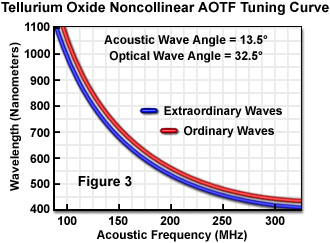
The most commonly employed AOTF design for spectral control in imaging systems is based on tellurium dioxide operated in noncollinear mode, and it is therefore useful to consider some operational characteristics of this device, which pertain to its typical applications. The wavelength tuning properties of the AOTF are of primary importance in the most common of these applications. The momentum (and phase) matching condition provides that the wavelength selected for diffraction is determined by the drive frequency applied to the acoustic transducer and the resulting acoustic wave frequency. Figure 3 illustrates a typical tuning curve for a tellurium dioxide noncollinear AOTF in the visible to near-infrared spectral range. The tuning relationship between selected wavelength and applied RF frequency is generally different for the two orthogonally polarized output beams, and each is characterized by a separate mathematical expression. The center transmission wavelength decreases with increasing acoustic frequency. The frequency and tuned wavelength vary in approximate inverse fashion, although this is not exact due to the fact that the ratio of refractive indices for the ordinary and extraordinary rays also varies with wavelength. The wavelength difference between the two output rays varies from several nanometers to tens of nanometers, depending on the device configuration. The relevant design parameters determining the AOTF crystal tuning relationship are the angles of the acoustic wave propagation relative to the [110] axis and the incident light input relative to the optical axis, typically designated as α and θ(i), respectively. For some combinations of these device angles, if the incident light is polarized, only one polarization component satisfies the noncritical phase matching condition, and the other exhibits a variation in tuning relationship with incident beam angle.
Acousto-optic tunable filters are limited in their wavelength tuning range by the electro-acoustic bandwidth of the piezoelectric transducer, which is typically an octave or less. This value is significantly less than the optical transmission range of the tuning crystal, and some commercially available AOTFs are provided with multiple transducers, designed for different bandwidths, to increase the tunable wavelength range. The extremely rapid tuning speed of the AOTF is one of its primary virtues for illumination control in microscopy, and this property is limited only by the acoustic wave's transit time in the crystal (equivalent to the transit distance divided by the acoustic velocity). In a noncollinear device, the acoustic transit distance is nominally equal to the optical aperture. Although higher acoustic velocity corresponds to greater tuning speed, the diffraction efficiency of some materials, including tellurium dioxide, varies as the inverse of the cube of acoustic velocity. Consequently, a lower acoustic velocity specification can be advantageous for devices such as AOTFs. For tellurium dioxide, longitudinal waves propagating along the direction have a velocity of over 4 kilometers per second, while in contrast, shear waves propagating parallel to travel at an abnormally low velocity of approximately 617 meters per second. Operation of such an AOTF in this "slow shear mode" provides improved diffraction efficiency while still exhibiting tuning response times of less than 10 microseconds. Tuning speeds for typical AOTFs of this design range from several microseconds to tens of microseconds depending on the aperture size (acoustic transit distance) and other configuration properties, such as characteristics of the transducer and its placement on the crystal.
The wavelength switching capabilities of the AOTF can be utilized to provide a rapidly tunable light source, which can be operated in a variety of modes that are applicable in optical microscopy. Single illumination wavelengths can be tuned sequentially or randomly accessed, and it is possible to output multiple wavelengths from the filter simultaneously. Unlike a conventional diffraction grating or prism, switching can be immediately performed between randomly specified wavelengths without scanning through intermediate wavelengths. Each tuned wavelength is directed to the device output by electronically switching to the corresponding RF drive frequency. If more than one RF drive frequency is applied to the piezoelectric transducer, the propagating variable acoustic wave is capable of diffracting multiple optical wavelengths simultaneously. The number and relative power of the radio frequencies driving the transducer can be varied rapidly to control the intensity and wavelength of the emitted light beams. The number of frequencies that can be employed simultaneously is determined by the power handling capacity of the piezoelectric transducer, and by the requirement of meeting the minimum power necessary for each diffracted wavelength when the total drive power is partitioned among the radio frequencies being applied. Commercially available AOTFs based on a noncollinear tellurium dioxide configuration, operating in the visible and near-infrared spectral range, are typically limited to 10 to 12 simultaneous output channels. With continuing technological advances in the development of low-power AOTFs, it is predicted that more than 100 controllable channels will be able with upcoming devices.
The spectral resolution of a tunable filter is defined as the full width at half-maximum of the main lobe from the selected optical output, and is a function of both wavelength and device configuration. The resolution (bandpass) of a typical AOTF ranges from several nanometers to tens of nanometers for the visible and near-infrared spectral regions, approximately one-thirtieth the value for ordinary Bragg diffraction. The design parameters that affect resolution include the dispersion constant of the crystalline material (related to degree of birefringence), the incidence angle, and the acousto-optic interaction length.
According to the current theory governing tuning characteristics of AOTFs, only light sources having a wavelength exactly satisfying the phase-matching condition are transmitted in the diffracted beam(s), for a device having infinite acousto-optic interaction length. In practice, however, the finite interaction length results in a broadening of the filter passband, which defines the spectral resolution of the device. In contrast to a diffraction grating, the full width at half-maximum of the AOTF transmission peak changes as a function of the square of the wavelength, resulting in a variable bandpass. When scanned over its full wavelength tuning range, a typical AOTF operating within the visible spectral region exhibits a bandpass specification that varies by approximately 2 to 6 nanometers.
In noncollinear AOTF designs, as previously discussed, the tuning relationship between the applied RF frequency and diffracted wavelength is different for the two orthogonally polarized first-order light beams. Consequently, their wavelengths are different and only one meets the noncritical phase-matching condition, which is desirable in order to maximize the device's angular field of view. In some applications requiring increased output intensity from the AOTF, it is advantageous to utilize combined diffracted outputs. Although it is possible with a standard AOTF to choose an input incidence angle relative to the fixed crystallographic axes and acoustic propagation direction that results in an equivalent tuning relationship for the two polarized beams, this strategy reduces spectral resolution. Special-purpose tellurium dioxide noncollinear AOTFs have also been fabricated with design parameters specifically chosen to produce diffracted outputs having the same tuning relationship, and with both satisfying the noncritical phase-matching condition in the near-infrared spectral region.
As applied in laser scanning confocal microscopy, one of the most significant benefits of the AOTF is its capability to replace much more complex and unwieldy filter mechanisms for controlling light transmission, and to apply intensity modulation for wavelength discrimination purposes. The ability to perform extremely rapid adjustments in the intensity and wavelength of the diffracted beam gives the AOTF unique control capabilities. By varying the illumination intensity at different wavelengths, the response of multiple fluorophores, for example, can be balanced for optimum detection and recording. In addition, digital signal processors along with phase and frequency lock-in techniques can be employed to discriminate emission from multiple fluorophores or to extract low-level signals from background.
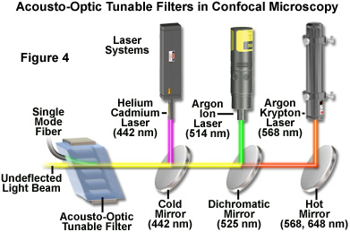
A practical light source configuration scheme utilizing an acousto-optic tunable filter for confocal microscopy is illustrated in Figure 4. The output of three laser systems (helium-cadmium, argon, and argon-krypton) are combined by dichromatic mirrors and directed through the AOTF, where the first-order diffracted beam (green) is collinear and is launched into a single-mode fiber. The undiffracted laser beams (green, yellow, and red) exit the AOTF at varying angles and are absorbed by a beam stop (not illustrated). The major lines (wavelengths) produced by each laser are indicated (in nanometers) beneath the hot and cold mirrors. The dichromatic mirror reflects wavelengths lower than 525 nanometers and transmits longer wavelengths. Two longer wavelength lines produced by the argon-krypton laser (568 and 648 nanometers) are reflected by the hot mirror, while the output of the argon laser (458, 476, 488, and 514 nanometers) is reflected by the dichromatic mirror and combined with the transmitted light from the argon-krypton laser. Output from the helium-cadmium laser (442 nanometers) is reflected by the cold mirror and combined with the longer wavelengths from the other two lasers, which are transmitted through the mirror.
Because of the rapid optical response from the AOTF crystal to the acoustic transducer, the acousto-optic interaction is subject to abrupt transitions resembling a rectangular rather than sinusoidal waveform. This results in the occurrence of sidelobes in the AOTF passband on either side of the central transmission peak. Under ideal acousto-optic conditions, these sidelobes should be symmetrical about the central peak, with the first lobe having 4.7 percent of the central peak's intensity. In practice, the sidelobes are commonly asymmetrical and exhibit other deviations from predicted structure caused by variations in the acousto-optic interaction, among other factors. In order to reduce the sidelobes in the passband to insignificant levels, several types of amplitude apodization of the acoustic wave are employed, including various window functions, which have been found to suppress the highest sidelobe by 30 to 40 decibels. One method that can be used in reduction of sidelobe level with noncollinear AOTFs is to apply spatial apodization by means of weighted excitation of the transducer. In the collinear AOTF, a different approach has been employed, which introduces an acoustic pulse, apodized in time, into the filter crystal.
The effective linear aperture of an AOTF is limited by the acoustic beam height in one dimension and by the acoustic attenuation across the optical aperture (the acoustic transit distance) in the other dimension. The height of the acoustic beam generated within the AOTF crystal is determined by the performance and physical properties of the acoustic transducer. Acoustic attenuation in crystalline materials such as tellurium dioxide is proportional to the square of acoustic frequency, and is therefore a more problematic limitation to linear aperture size in the shorter wavelength visible light range, which requires higher RF frequencies for tuning. Near-infrared and infrared radiation produces less restrictive limitations because of the lower acoustic frequencies associated with diffraction of these longer wavelengths.
The maximum size of an individual acoustic transducer is constrained by performance and power requirements in addition to the geometric limitations of the instrument configuration, and AOTF designers may use an array of transducers bonded to the crystal in order to increase the effective lateral dimensions of the propagating acoustic beam, and to enlarge the area of acousto-optic interaction. The required drive power is one of the most important variables in acousto-optic design, and generally increases with optical aperture and for longer wavelengths. In contrast to acoustic attenuation, which is reduced in the infrared spectral range, the higher power required to drive transducers for infrared AOTFs is one of the greatest limitations in these devices. High drive power levels result in heating of the crystal, which can cause thermal drift and instability in the filter performance. This is particularly a problem when acoustic power and frequency are being varied rapidly over a large range, and the crystal temperature does not have time to stabilize, producing transient variations in refractive index. If an application requires wavelength and intensity stability and repeatability, the AOTF should be maintained at a constant temperature. One approach taken by equipment manufacturers to minimize this problem is to heat the crystal above ambient temperature, to a level at which it is relatively unaffected by the additional thermal input of the transducer drive power. An alternative solution is to house the AOTF in a thermoelectrically cooled housing that provides precise temperature regulation. Continuing developmental efforts promise to lead to new materials that can provide relatively large apertures combined with effective separation of the filtered and unfiltered beams without use of polarizers, while requiring a fraction of the typical device drive power.
In a noncollinear AOTF, which spatially separates the incident and diffracted light paths, the deflection angle (the angle separating diffracted and undiffracted light beams exiting the crystal) is an additional factor limiting the effective aperture of the device. As discussed previously, the deflection angle is greater for crystals having greater birefringence, and determines in part the propagation distance required for adequate separation of the diffracted and undiffracted beams to occur after exiting the crystal. The required distance is increased for larger entrance apertures, and this imposes a practical limit on maximum aperture size because of constraints on the physical dimensions of components that can be incorporated into a microscope system. The angular aperture is related to the total light collecting power of the AOTF, an important factor in imaging systems, although in order to realize the full angular aperture without the use of polarizers in the noncollinear AOTF, its value must be smaller than the deflection angle.
Because the acousto-optic tunable filter is not an image-forming component of the microscope system (because it is typically employed for source filtering), there is no specific means of evaluating the spatial resolution for this type of device. However, the AOTF may restrict the attainable spatial resolution of the imaging system because of its limited linear aperture size and acceptance angle, in the same manner as other optical components. Based on the Rayleigh criterion and the angular and linear apertures of the AOTF, the maximum number of resolvable image elements may be calculated for a given wavelength, utilizing different expressions for the polar and azimuthal planes. Although diffraction limited resolution can be attained in the azimuthal plane, dispersion in the AOTF limits the resolution in the polar plane, and measures must be taken to suppress this factor for optimum performance. The dependence of deflection angle on wavelength can produce one form of dispersion, which is typically negligible when tuning is performed within a relatively narrow bandwidth, but significant in applications involving operation over a broad spectral range. Changes in deflection angle with wavelength can result in image shifts during tuning, producing errors in techniques such as ratio imaging of fluorophores excited at different wavelengths, and in other multi-spectral applications. When the image shift obeys a known relationship to wavelength, corrections can be applied through digital processing techniques. Other effects of dispersion, including reduced angular resolution, may result in image degradation, such as blurring, that requires more elaborate measures to suppress.
Summary of AOTF Benefits in Confocal Microscopy
Considering the underlying principles of operation and performance factors that relate to the application of AOTFs in imaging systems, a number of virtues from such devices for light control in fluorescence confocal microscopy are apparent. Several benefits of the AOTF combine to greatly enhance the versatility of the latest generation of confocal instruments, and these devices are becoming increasing popular for control of excitation wavelength ranges and intensity. The primary characteristic that facilitates nearly every advantage of the AOTF is its capability to allow the microscopist control of the intensity and/or illumination wavelength on a pixel-by-pixel basis while maintaining a high scan rate. This single feature translates into a wide variety of useful analytical microscopy tools, which are even further enhanced in flexibility when laser illumination is employed.
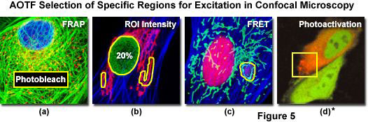
One of the most useful AOTF functions allows the selection of small user-defined specimen areas (commonly termed regions of interest; ROI) that can be illuminated with either greater or lesser intensity, and at different wavelengths, for precise control in photobleaching techniques, excitation ratio studies, resonance energy transfer investigations, or spectroscopic measurements (see Figure 5). The illumination intensity can not only be increased in selected regions for controlled photobleaching experiments, but can be attenuated in desired areas in order to minimize unnecessary photobleaching. When the illumination area is under AOTF control, the laser exposure is restricted to the scanned area by default, and the extremely rapid response of the device can be utilized to provide beam blanking during the flyback interval of the galvanometer scanning mirror cycle, further limiting unnecessary specimen exposure. In practice, the regions of excitation are typically defined by freehand drawing or using tools to produce defined geometrical shapes in an overlay plane on the computer monitor image. Some systems allow any number of specimen areas to be defined for laser exposure, and the laser intensity to be set to different levels for each area, in intensity increments as small as 0.1 percent. When the AOTF is combined with multiple lasers and software that allows time course control of sequential observations, time-lapse experiments can be designed to acquire data from several different areas in a single experiment, which might, for example, be defined to correspond to different cellular organelles.
Figure 5 illustrates several examples of user-defined regions of interest (ROIs) that were created for advanced fluorescence applications in laser scanning confocal microscopy. In each image, the ROI is outlined with a yellow border. The rat kangaroo cell (PtK2 line) presented in Figure 5(a) has a rectangular area in the central portion of the cytoplasm that has been designated for photobleaching experiments. Fluorophores residing in this region can be selectively destroyed by high power laser intensity, and the subsequent recovery of fluorescence monitored for determination of diffusion coefficients. Several freehand ROIs are illustrated in Figure 5(b), which can be targets for selected illumination intensities or photobleaching experiments. Fluorescence emission ratios in resonance energy transfer (FRET) can be readily determined using selected regions in confocal microscopy by observing the effect of bleaching the acceptor fluorescence in these areas (Figure 5(c); Indian Muntjac cells with yellow fluorescent protein). AOTF control of laser excitation in selected regions with confocal microscopy is also useful for investigations of protein diffusion in photoactivation studies using fluorescent proteins, as illustrated in Figure 5(d)*. This image frame presents the fluorescence emission peak of the Kaede protein as it shifts from green to red in HeLa (human cervical carcinoma) cells using selected illumination (yellow box) with a 405-nanometer violet-blue diode laser.
The rapid intensity and wavelength switching capabilities of the AOTF enable sequential line scanning of multiple laser lines to be performed in which each excitation wavelength can be assigned a different intensity in order to balance the various signal levels for optimum imaging. Sequential scanning of individual lines minimizes the time differential between signal acquisitions from the various fluorophores while reducing crossover, which can be a significant problem with simultaneous multiple-wavelength excitation (see Figure 6). The synchronized incorporation of multiple fluorescent probes into living cells has grown into an extremely valuable technique for study of protein-protein interactions, and the dynamics of macromolecular complex assembly. The refinement of techniques for incorporating green fluorescent protein (GFP) and its numerous derivatives into the protein-synthesizing mechanisms of the cell has revolutionized living cell experimentation. A major challenge in multiple-probe studies using living tissue is the necessity to acquire the complete multispectral data set quickly enough to minimize specimen movement and molecular changes that might distort the true specimen geometry or dynamic sequence of events. The AOTF provides the speed and versatility to control the wavelength and intensity illuminating multiple specimen regions, and to simultaneously or sequentially scan each at sufficient speed to accurately monitor dynamic cellular processes.
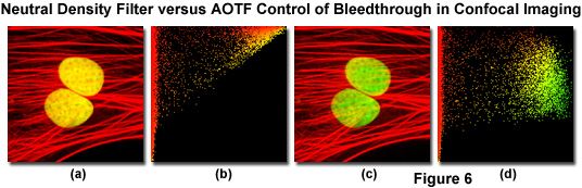
A comparison between the application of AOTFs and neutral density filters to control spectral separation of fluorophores in confocal microscopy is presented in Figure 6. The specimen is a monolayer culture of adherent Indian Muntjac deer skin fibroblast cells stained with Alexa Fluor 568 conjugated to phalloidin (targeting the filamentous actin network) and SYTOX Green (staining DNA in the nucleus). A neutral density filter that produces the high excitation signals necessary for both fluorophores leads to a significant amount of bleed-through of the SYTOX Green emission into the Alexa Fluor 568 channel (Figure 6(a); note the yellow nuclei). The high degree of colocalization between SYTOX Green and Alexa Fluor 568 is clearly illustrated by the scatterplot in Figure 6(b). The two axes in the scatterplot represent the SYTOX Green (abscissa) and the Alexa Fluor 568 (ordinate) channels. In order to balance the excitation power levels necessary to selectively illuminate each fluorophore with greater control of emission intensity, an AOTF was utilized to selectively reduce the SYTOX Green excitation power (Argon-ion laser line at 488 nanometers). Note the subsequent reduction in bleed-through as manifested by green color in the cellular nuclei in Figure 6(c). The corresponding scatterplot (Figure 6(d)) indicates a dramatically reduced level of bleed-through of SYTOX Green into the Alexa Fluor 568 channel.
The development of the AOTF has provided substantial additional versatility to techniques such as fluorescence recovery after photobleaching (FRAP), fluorescence loss in photobleaching (FLIP), as well as in localized photoactivated fluorescence (uncaging) studies (see Figure 5). The FRAP technique was originally conceived to measure diffusion rates of fluorescently tagged proteins in organelles and cell membranes. In the conventional FRAP procedure, a small spot on the specimen is continuously illuminated at a low light flux level and the emitted fluorescence is measured. The illumination level is then increased to a very high level for a brief time to destroy the fluorescent molecules in the illuminated region by rapid bleaching. After the light intensity is returned to the original low level, the fluorescence is monitored to determine the rate at which new unbleached fluorescent molecules diffuse into the depleted region. The technique, as typically employed, has been limited by the fixed geometry of the bleached region, which is often a diffraction-limited spot, and by having to mechanically adjust the illumination intensity (using shutters or galvanometer-driven components). The AOTF not only allows near-instantaneous switching of light intensity, but also can be utilized to selectively bleach randomly specified regions of irregular shape, lines, or specific cellular organelles, and to determine the dynamics of molecular transfer into the region.
By enabling precise control of illuminating beam geometry and rapid switching of wavelength and intensity, the AOTF is a significant enhancement to application of the FLIP technique in measuring the diffusional mobility of certain cellular proteins. This technique monitors the loss of fluorescence from continuously illuminated localized regions and the redistribution of fluorophore from distant locations into the sites of depletion. The data obtained can aid in the determination of the dynamic interrelationships between intracellular and intercellular components in living tissue, and such fluorescence loss studies are greatly facilitated by the capabilities of the AOTF in controlling the microscope illumination.
The method of utilizing photoactivated fluorescence has been very useful in studies such as those examining the role of calcium ion concentration in cellular processes, but has been limited in its sensitivity to localized regional effects in small organelles or in close proximity to cell membranes. Typically, fluorescent species that are inactivated by being bound to a photosensitive species (referred to as being caged) are activated by intense illumination that frees them from the caging compound and allows them to be tracked by the sudden appearance of fluorescence. The use of the AOTF has facilitated the refinement of such studies to assess highly localized processes such as calcium ion mobilization near membranes, made possible because of the precise and rapid control of the illumination triggering the activation (uncaging) of the fluorescent molecule of interest.
Because the AOTF functions, without use of moving mechanical components, to electronically control the wavelength and intensity of multiple lasers, great versatility is provided for external control and synchronization of laser illumination with other aspects of microscopy experiments. When the confocal instrument is equipped with a controller module having input and output trigger terminals, laser intensity levels can be continuously monitored and recorded, and the operation of all laser functions can be controlled to coordinate with other experimental specimen measurements, automated microscope stage movements, sequential time-lapse recording, and any number of other operations.
*Although it became one of the most important cell lines in medical research, it’s imperative that we recognize Henrietta Lacks’ contribution to science happened without her consent. This injustice, while leading to key discoveries in immunology, infectious disease, and cancer, also raised important conversations about privacy, ethics, and consent in medicine.
To learn more about the life of Henrietta Lacks and her contribution to modern medicine, click here.
http://henriettalacksfoundation.org/
Sorry, this page is not
available in your country.