Darkfield Illumination
All of us are quite familiar with the appearance and visibility of stars on a dark night, this despite their enormous distances from the Earth. Stars can be readily observed at night primarily because of the stark contrast between their faint light and the black sky.
Yet stars are shining both night and day, but they are invisible during the day because the overwhelming brightness of the sun "blots out" the faint light from the stars, rendering them invisible. During a total solar eclipse, the moon moves between the Earth and the sun blocking out the light of the sun and the stars can now be seen even though it is daytime. In short, the visibility of the faint star light is enormously enhanced against a dark background.
This principle is applied in darkfield (also called darkground) microscopy, a simple and popular method for making unstained transparent specimens clearly visible. Such objects often have refractive indices very close in value to that of their surroundings and are difficult to image in conventional brightfield microscopy. For instance, many small aquatic organisms have a refractive index ranging from 1.2 to 1.4, resulting in a negligible optical difference from the surrounding aqueous medium. These are ideal candidates for darkfield illumination.
Darkfield illumination requires blocking out of the central light which ordinarily passes through and around (surrounding) the specimen, allowing only oblique rays from every azimuth to "strike" the specimen mounted on the microscope slide. The top lens of a simple Abbe darkfield condenser is spherically concave, allowing light rays emerging from the surface in all azimuths to form an inverted hollow cone of light with an apex centered in the specimen plane. If no specimen is present and the numerical aperture of the condenser is greater than that of the objective, the oblique rays cross and all such rays will miss entering the objective because of their obliquity. The field of view will appear dark.
Specimen Imaging in Darkfield Condensers
Explore how a specimen reflects, refracts, and diffracts light emitted from the hollow cone of light produced by a darkfield condenser.
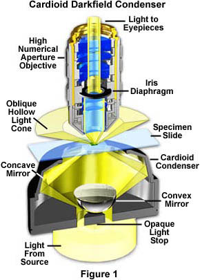
The darkfield condenser/objective pair illustrated in Figure 1 is a high-numerical aperture arrangement that represents darkfield microscopy in its most sophisticated configuration, which will be discussed in detail below. The objective contains an internal iris diaphragm that serves to reduce the numerical aperture of the objective to a value below that of the inverted hollow light cone emitted by the condenser. The cardioid condenser is a reflecting darkfield design that relies on internal mirrors to project an aberration-free cone of light onto the specimen plane.
When a specimen is placed on the slide, especially an unstained, non-light absorbing specimen, the oblique rays cross the specimen and are diffracted, reflected, and/or refracted by optical discontinuities (such as the cell membrane, nucleus, and internal organelles) allowing these faint rays to enter the objective. The specimen can then be seen bright on an otherwise black background. In terms of Fourier optics, darkfield illumination removes the zeroth order (unscattered light) from the diffraction pattern formed at the rear focal plane of the objective. This results in an image formed exclusively from higher order diffraction intensities scattered by the specimen.
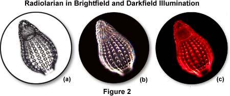
The photomicrographs in Figure 2 illustrate the effects of darkfield and brightfield illumination on silica skeletons from a small marine protozoan (radiolarian) in a whole mount specimen. In ordinary brightfield, skeletal features of the radiolarian are not well defined and tend to be washed out in photomicrographs recorded either with traditional film or digitally captured. The photomicrograph in Figure 2(a) was taken in brightfield illumination with the condenser aperture diaphragm closed to a point where diffraction artifacts obscure some of the sample detail. This enhances specimen contrast at the expense of image distortion. Under darkfield illumination (Figure 2(b)), more detail is present, especially in the upper portion of the organism, and the image acquires an apparent three-dimensional appearance. When a red filter is used in conjunction with a darkfield stop (Figure 2(c)), the radiolarian takes on a colorful appearance that is more pleasing, although no additional detail is produced and there is even some reduction in image quality.
Specimens that have smooth reflective surfaces produce images due, in part, to reflection of light into the objective. In situations where the refractive index is different from the surrounding medium or where refractive index gradients occur (as in the edge of a membrane), light is refracted by the specimen. Both instances of reflection and refraction produce relatively small angular changes in the direction of light, allowing some to enter the objective. In contrast, some light striking the specimen is also diffracted, producing a 180-degree arc of light that passes through the entire numerical aperture range of the objective. The resolving power of the objective is the same in darkfield illumination as observed under brightfield conditions, but the optical character of the image is not as faithfully reproduced (except when a specially-designed iris diaphragm is utilized to lower the effective numerical aperture with high-magnification oil immersion objectives designed specifically for darkfield microscopy).
As in the example of starlight described above, the visibility is greatly enhanced by the contrast between the brightly shining specimen and the dark surround. As discussed above, what has happened in darkfield illumination is that all the ordinarily undeviated rays of the zeroth order have been blocked by the opaque stop. Oblique rays, now diffracted by the specimen and yielding first, second, and higher diffracted orders at the rear focal plane of the objective, proceed onto the image plane where they interfere with one another to produce an image of the specimen.
Ideal candidates for darkfield illumination include minute living aquatic organisms, diatoms, small insects, bone, fibers, hair, unstained bacteria, yeast, cells in tissue culture, and protozoa. Non-biological specimens include mineral and chemical crystals, colloidal particles, dust-count specimens, and thin sections of polymers and ceramics containing small inclusions, porosity differences, or refractive index gradients. Care should be taken when preparing specimens for darkfield microscopy because features that lie above and below the plane of focus can also scatter light and contribute to image degradation. Specimen thickness and microscope slide thickness are also very important and, in general, a thin specimen is desirable to eliminate the possibility of diffraction artifacts that can interfere with image formation.
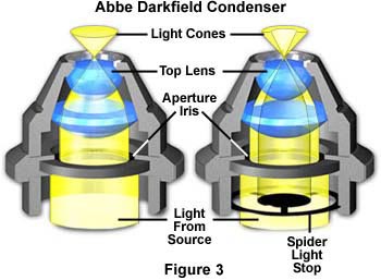
The substage condensers illustrated in Figure 3 demonstrate the effect of an opaque stop on light pathways through a simple refracting condenser. On the left (Figure 3(a)), is a typical Abbe brightfield condenser positioned with the aperture diaphragm opened to maximize the numerical aperture of the light cone. Light from the source passes through the aperture diaphragm and is then refracted through several lens elements to form an inverted cone of light with a numerical aperture of approximately 1.20. When an opaque spider-style light stop (Figure 3(b)) is inserted below the completely opened aperture diaphragm, the central light rays are blocked, allowing only peripheral light rays to pass through the lenses to form an inverted oblique hollow cone of light with no change in numerical aperture (1.20). The illuminating hollow light cone is formed by refraction of light at perimeter of the lens elements, where optical correction is often poorest. Even so, this condenser will perform adequately using low magnification objectives, and produces very nice results for qualitative darkfield work. For more exacting quantitative microscopy, it is necessary to use aplanatic condensers (corrected for both chromatic and spherical aberrations), which perform much better by producing images with clearer detail and more reliable features.
In a darkfield microscope, if you were to look at the back of the objective through a Bertrand lens or phase telescope, it would appear filled with light. This faint diffracted light is reconstituted into the visible image at the plane of the eyepiece diaphragm with its contrast reversed, bright image on black background. Since darkfield microscopy eliminates the bright undeviated light, this form of illumination is very wasteful of light and thus demands a high intensity illumination source. Microscope slides must be of the appropriate thickness, approximately one millimeter +/- 0.1 mm. Specimen slides and all optical surfaces in the light path must be scrupulously clean because every dirt speck will be mercilessly bright.
Abbe Darkfield Condensers
Discover how changing the opaque stop size affects light cone formation and numerical aperture in a simple Abbe condenser.
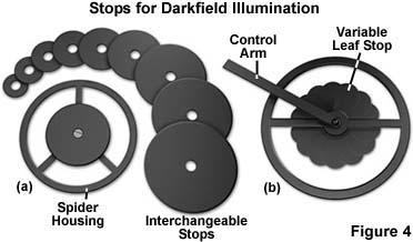
There are several pieces of equipment that are utilized to produce darkfield illumination. The simplest is a "spider stop" placed just under the bottom lens (in the front focal plane) of the substage condenser (Figures 3(b) and 4(a)). Both the aperture and field diaphragms are opened wide to pass oblique rays. The central opaque stop (you can make one by mounting a coin on a clear glass disk) blocks out the central rays. This device works fairly well, even with the Abbe condenser (Figure 3), with the 10x objective up to 40x or higher objectives having a numerical aperture no higher than 0.65. The diameter of the opaque stop should be approximately 16-18 millimeters for a 10x objective of numerical aperture 0.25 to approximately 20-24 millimeters for 20x and 40x objectives of numerical apertures approaching 0.65.
The set of stops illustrated in Figure 4(a) vary in size from 8 millimeters to 30 millimeters and provide excellent darkfield opaque stops for virtually any numerical aperture objective (below 0.65). Individual stops can be interchanged simply by removing the screw in the bottom of the support spider and replacing the stop with a new size. The outer size of the spider holder will vary depending upon the housing opening diameter at the bottom of the condenser.
The light stop illustrated in Figure 4(b) is an ingenious device that expands and contracts a "reverse iris" diaphragm to increase or decrease the size of the stop using a lever control arm. As this lever is turned, the size of the central leaves changes from about 10 millimeters to 25 millimeters in diameter, creating a larger stop for higher magnification objectives. This type of variable light stop diaphragm eliminates the need for changing light stops each time a higher power objective is inserted into the optical path. It also has the additional advantage of being "tunable" for slight differences in the stop diameter necessary to achieve the best performance while observing the specimen. Although these types of diaphragm light stops are now very rare, they do provide a unique method of achieving highly desirable effects with darkfield illumination.
Darkfield Microscopy at High Magnifications
For more precise work and blacker backgrounds, you may choose a condenser designed especially for darkfield, i.e. to transmit only oblique rays. There are several varieties: "dry" darkfield condensers with air between the top of the condenser and the underside of the slide--and immersion darkfield condensers which require the use of a drop of immersion oil (some are designed to use water instead) establishing contact between the top of the condenser and the underside of the specimen slide. The immersion darkfield condenser has internal mirrored surfaces and passes rays of great obliquity and free of chromatic aberration, producing the best results and blackest background.
Perhaps the most widely used darkfield condenser is the paraboloid, consisting of a solid piece of glass ground very accurately into the shape of a paraboloid, as illustrated in Figure 5(b). Light incident upon the reflecting surface (between the glass and condenser housing in Figure 5(b)) of a paraboloid condenser will be focused at the focal point of the reflector. Most paraboloid condensers are cut to ensure that the focal point is slightly beyond the top of the condenser so that parallel light rays will be focused at a position that maximizes illumination of the specimen. The light stop at the bottom of the glass condenser serves to block central rays from reaching the specimen. Light rays that are reflected by the condenser are angled higher than the critical angle of reflection and converge at the principal focus of the condenser. The combination of a glass slide, mounting medium, and immersion oil (between the condenser and the microscope slide) complete the optical homogeneity of the paraboloid shape.
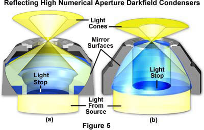
As discussed above, the dry darkfield condenser is useful for objectives with numerical apertures below 0.75 (Figure 5(a)), while the paraboloid and cardioid immersion condensers (Figures 1 and 5(b)) can be used with objectives of very high numerical aperture (up to 1.4). Objectives with a numerical aperture above 1.2 will require some reduction of their working aperture since their maximum numerical aperture may exceed the numerical aperture of the condenser, thus allowing direct light to enter the objective. For this reason, many high numerical aperture objectives designed for use with darkfield as well as brightfield illumination are made with a built-in adjustable iris diaphragm that acts as an aperture stop. This reduction in numerical aperture also limits the resolving power of the objective as well as the intensity of light in the image. Specialized objectives designed exclusively for darkfield work are produced with a maximum numerical aperture close to the lower limit of the numerical aperture of the darkfield condenser. They do not have internal iris diaphragms, however the lens mount diameters are adjusted so at least one internal lens has the optimum diameter to perform as an aperture stop.
Table 2 lists several properties of the most common reflecting high numerical aperture darkfield condensers. This table should be used as a guide when selecting condenser/objective combinations for use with high numerical aperture darkfield applications.
High Numerical Aperture Darkfield Condenser Specifications
Condenser Type Hollow ConeNumerical Aperture Objective MaximumNumerical Aperture Number of ReflectingSurfaces Optical Corrections Paraboloid 1.00-1.40 0.85 1 Parabolic Achromatic Cardioid 1.20-1.30 1.05 1 Spherical1 Cardioidal Achromatic/Aplanatic Bicentric 1.20-1.30 1.05 1 Cardioidal1 Spherical Aplanatic Bispheric 1.20-1.30 1.05 2 Spherical Aplanatic Cassegrain 1.40-1.50 1.30 1 Aspheric1 Spherical Aplanatic Spot Ring(Bicentric) 1.40-1.50 1.30 2 Spherical Aplanatic NelsonCassegrain 1.30-1.45 1.20 1 Aspheric1 Spherical Aplanatic
| Condenser Type | Hollow Cone Numerical Aperture | Objective Maximum Numerical Aperture | Number of Reflecting Surfaces | Optical Corrections |
| Paraboloid | 1.00-1.40 | 0.85 | 1 Parabolic | Achromatic |
| Cardioid | 1.20-1.30 | 1.05 |
1 Spherical
1 Cardioidal |
Achromatic/
Aplanatic |
| Bicentric | 1.20-1.30 | 1.05 |
1 Cardioidal
1 Spherical | Aplanatic |
| Bispheric | 1.20-1.30 | 1.05 | 2 Spherical | Aplanatic |
| Cassegrain | 1.40-1.50 | 1.30 |
1 Aspheric
1 Spherical | Aplanatic |
| Spot Ring (Bicentric) | 1.40-1.50 | 1.30 | 2 Spherical | Aplanatic |
| Nelson Cassegrain | 1.30-1.45 | 1.20 |
1 Aspheric
1 Spherical | Aplanatic |
Table 2
The condensers illustrated in Figure 5 are designed specifically to produce oblique hollow light cones of high numerical aperture for darkfield illumination. In both instances, the upper surface of the condenser is planar and perpendicular to the optical axis of the microscope. The condenser on the left (Figure 5(a)) is designed to be used "dry" with no oil between the condenser and the underside of the microscope slide. In contrast, the paraboloid condenser in Figure 5(b) is intended to be "oiled" to the bottom of the microscope slide, directly underneath the specimen. Omission of immersion oil when using this condenser (or any of the other condensers listed in Table 2) will preclude any light from reaching the specimen. The oblique hollow cone of light rays emitted by these condensers cannot emerge from the top lens without oil and will be totally reflected back into the condenser. Light emitted from the illumination source is reflected at the mirrored glass surfaces within the interior of the condensers and exits the top of the condensers at much higher angles of inclination than the critical angle (approximately 41 degrees) at which total reflection occurs for passage of light from glass to air. In the situation of the oiled paraboloid condenser (Figure 5(b) and the condensers in Table 2) where the refractive index of the condenser glass, immersion oil, and glass slide are equal, light emitted from the condenser passes through the specimen unrefracted by glass-air interfaces.
Hollow Light Cone Numerical Aperture
Use this tutorial to visualize how the hollow cone of light changes with numerical aperture in reflecting darkfield condensers.
Reflecting high numerical aperture condensers listed in Table 2 cover a wide range of designs used to produce the oblique hollow cone of light necessary for high-magnification darkfield microscopy. The paraboloid darkfield condenser has been discussed in detail above. Another very useful design is the cardioid condenser that is illustrated in Figure 1. This condenser design utilizes a mirrored hemisphere in the center of the condenser that serves as both a light stop and a reflector to direct light onto a second reflecting surface shaped to resemble a cardioid of revolution, from which the condenser derives its name. The combination of spherical and cardioid reflecting surfaces produces a condenser that is free from coma and both spherical and chromatic aberration. There are several technical drawbacks to using a condenser of such high numerical aperture. The cardioid condenser is very sensitive to alignment and must be carefully positioned to take advantage of the very sharp cone of illumination, making it the most difficult darkfield condenser to use. In addition, the condenser produces a significant amount of glare, even from the most minute dust particles, and the short focal length may result in poor illumination on objects that exceed a few microns in size or thickness. When choosing microscope slides for quantitative high-magnification darkfield microscopy, make certain to select slides made from a glass mixture that is free of fluorescent impurities.
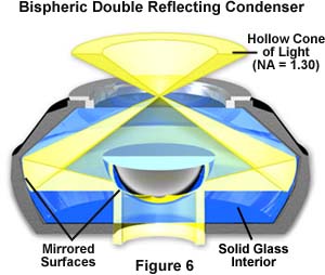
High numerical aperture reflecting condensers (Figures 1, 5, 6 and Table 2) with darkfield illumination provide the method of choice for observing and photographing collections of very small particles or colloidal suspensions, even when the particle diameter is significantly lower than the limit of resolution for the objective. This is due to light diffracted by the particles, which passes through the objective and becomes visible as bright diffraction disks. Each particle is visible as a minute diffraction disk, provided the lateral distance between adjacent particles is greater than the limit of resolving power of the objective. As illumination intensity is increased, the optical difference between minute diffracting particles and their background increases. Simultaneously, even smaller particles (detectable solely by their ability to scatter light) now diffract enough light to become visible and suspended particles can be seen even when their diameters are smaller than 40 nanometers, which is about one-fifth the 200 nanometer resolution limit with oil immersion objectives of the highest numerical aperture. In biological applications, the movements of living bacterial flagella that average about 20 nanometers in diameter (too small to be seen in brightfield or DIC illumination) can be observed and photographed using high numerical aperture darkfield condensers.
Careful attention should be paid to the details of oiling a high numerical aperture condenser to the bottom of the specimen slide. It is very difficult to avoid introduction of tiny air bubbles into the area between the condenser top lens and the bottom of the microscope slide, and this technique should be practiced to perfection. Air bubbles will cause image flare and distortion, leading to a loss of contrast and overall image degradation. Problems are also encountered when using microscope slides that are either too thick or too thin. Many darkfield condensers contain the range of usable slide thickness inscribed directly on the condenser mount. If the slide is too thick, it is often difficult to focus the condenser without resorting to a higher viscosity immersion oil. On the other hand, slides that are too thin have a tendency to break the oil bond between the condenser and the slide. It is a good idea to purchase precision microscope slides of the correct thickness to avoid any of the problems mentioned above.
Darkfield Condenser Adjustment
Explore how alignment and configuration of a darkfield condenser affects image quality.
A unique situation arises when specimens immersed in aqueous medium are being imaged using a high numerical aperture darkfield condenser. Under these conditions the refractive index of the aqueous solution limits the angle of inclination under which light can pass from the glass microscope slide (n = 1.515) into the water (n = 1.336) surrounding the specimen. The maximum numerical aperture of light passing from glass to water is given by the following equation:
NA (illumination) = 1.555 × sin(i) = 1.336 × sin(90°)
and because sin(90°) = 1
NA (illumination) = 1.336
Even though reflecting darkfield condensers designed for oil immersion are listed with upper limits of numerical aperture as high as 1.50 (see Table 2), light contributing to the illumination of specimens in aqueous media must have a numerical aperture no greater than 1.336, reducing the effective upper limit of darkfield illumination. In the case of specimens immersed in liquids of higher refractive index, the effective upper limit of the numerical aperture of darkfield illumination can approach a maximum of 1.50, although this is difficult to achieve in practice.
High numerical aperture condensers, whether intended for use dry or with oil, must be accurately centered in the optical path of the microscope to realize optimum performance. To achieve this, many darkfield condensers are built with a small circle engraved onto the upper surface to aid in centering the condenser. Centering is performed with a low power (10x-20x) objective by imaging the engraved circle and using the condenser centering screws to ensure the circle (and condenser) are correctly centered in the optical path. For more detailed information about microscope alignment for darkfield illumination, consult our section on darkfield microscope configuration elsewhere in the microscopy primer.
In general, objects imaged under proper conditions of darkfield illumination are quite spectacular to see (e.g. try a drop of fresh blood in darkfield). Often specimens containing very low inherent contrast in brightfield microscopy shine brilliantly in darkfield. Such illumination is best for revealing outlines, edges, boundaries, and refractive index gradients. Unfortunately, darkfield illumination is less useful in revealing internal details.
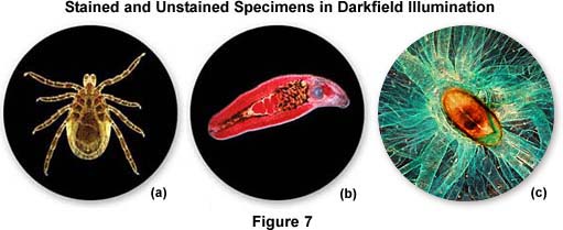
Other types of specimens, including many that are stained, also respond well to illumination under darkfield conditions. Figure 7 illustrates darkfield photomicrographs of three types of specimen, all of which produce good contrast in both brightfield and darkfield illumination. Details in the body of the deer tick (Ixodes demmini) shown in Figure 7(a) can be washed out in brightfield, unless the condenser aperture is stopped down to maximize contrast. However, in darkfield, most of the specimen detail in the tick becomes visible and can be easily captured on film. The heavily stained helminth trematode (Echinostoma revolutum, Figure 7(b)) also reveals considerably more detail when illuminated under darkfield conditions, as does the silkworm trachea and spiracle illustrated in Figure 7(c). In addition to the examples presented above, a number of other specimens can also be viewed and photographed under both brightfield and darkfield illumination to achieve the desired effects.
During the first half of the Twentieth Century, darkfield microscopy had a very strong following and much effort was expended in optimizing darkfield condensers and illuminators. This intense interest slowly began to fade with the emergence of more advanced contrasting-enhancing techniques such as phase contrast, differential interference contrast, and Olympus relief contrast.
Darkfield microscopy is still an excellent tool for both biological and medical investigations. It can be effectively used at high magnifications to photograph living bacteria, or at low magnifications to view and photograph cells, tissues, and whole mounts. Marine biologists continue to use darkfield illumination at low powers to observe and record data about fresh and salt water organisms such as algae and plankton.
Sorry, this page is not
available in your country.