Optimization and Troubleshooting
A key feature of fluorescence microscopy is its ability to detect fluorescent objects that are sometimes faintly visible or even very bright relative to the dark (often black) background. In order to optimize this feature, image brightness and resolution must be maximized using the principles that will be discussed in this portion of the primer.
Image Brightness - One of the most important aspects of optimizing image brightness is to ensure that the sample is supplied with sufficient light energy for excitation at the appropriate wavelength for each chromophore attached to the specimen. Equally important is selection of the proper barrier filter to maximize the amount of emitted fluorescence directed to the observation tubes or camera tube. High-energy light sources such as mercury and xenon burners will provide a large amount of excitation energy in very narrow ranges of near ultraviolet and visible light. When the use of these light sources is coupled to the proper selection of excitation filters that are able to transmit selected wavelengths while blocking those that are undesirable, then the optimal criteria for excitation will be met.
The selection of barrier filters that prevent unwanted wavelengths from entering the observation tubes is a primary concern. The total energy of excitation is far greater than the energy of emission, therefore it is important to choose an efficient barrier filter that will block out unwanted wavelengths while allowing fluorescent emission from the sample to pass. Objectives chosen for fluorescence must be able to transmit light effectively both in the near ultraviolet region and throughout the visible spectrum.
In view of the low emitted light levels, the role of the objective in fluorescence microscopy is crucial because it is the objective's function to gather light from the specimen. The angle of the cone of light accepted by the objective is determined by the numerical aperture (N.A.) of the objective, as illustrated in Figure 1. In transmitted light fluorescence microscopy, the intensity of the light reaching the eye or other detector varies directly as the square of the numerical aperture of the objective and the condenser and inversely as the square of the total magnification.
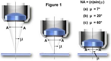
On the other hand, in reflected light fluorescence, the intensity of the image varies directly as the fourth power of the numerical aperture of the objective in use, as well as inversely as the square of the numerical total magnification:
This difference comes as a result of the objective's initially functioning as a condenser for concentrating light on the specimen, and then as the usual light gatherer for image formation. The implications are clear: high numerical aperture objectives will yield images of much higher intensity than will identical magnification objectives with lower numerical aperture. For example, other things being equal, a 40X objective with an N.A. of 1.0 will yield images more than five times brighter than a 40X objective with a numerical aperture of 0.65. A further implication is that, if possible, the employment of lower magnification visual eyepieces (e.g. 8X magnification) will also increase the brightness of the image as compared to the more commonly used 10X observation eyepieces. Additionally, in reflected light fluorescence, the excitation light is concentrated by the objective (in its function as a condenser) only on the area being observed. As a result the intensity of the excitation light is much higher than in transmitted light darkfield fluorescence where the area being excited does not change as objectives are changed. Also in darkfield, the numerical aperture of the objective must be reduced to below that of the condenser to preserve the darkness of the field of view.
In addition to numerical aperture being an important consideration, it is advisable to have objectives of highest quality chromatic correction since the focusing of the various colors in the same plane will yield sharper images. Further, the better the spherical correction, the sharper the image. Thus, the objectives of choice are planapochromats or planfluorites. These should be designed so that the lens elements and their cements will not themselves autofluoresce when irradiated with light below 400 nanometers in wavelength (light in the near ultraviolet).
When possible, oil-immersion objectives should be employed to minimize the loss of light caused by reflection from the glass slide and coverslip surfaces. Modern microscope manufacturers strive to provide optical elements that are completely free of autofluorescent contaminants, but this aspect should also be taken into consideration as autofluorescence will decrease sample contrast by increasing background brightness.
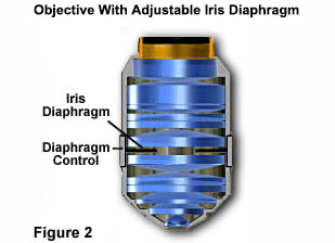
Image Resolution - The Royal Microscopical Society (RMS) standard thickness for glass coverslips if 0.17mm. There is a slight degree of variation in this number (usually between 0.01mm and 0.03mm) in a statistical sampling of coverslips due to fluctuations in the manufacturing process. High numerical aperture "dry" objectives are the most susceptible to these variations and many are provided with correction collars to allow the microscopist to fine-tune objective correction for cover glass thickness. It is very important to purchase highly accurate coverslips and to make sure that objective correction collars are adjusted optimally. In addition, some manufacturers offer specialized objectives that contain an internal iris diaphragm as illustrated with the Olympus objective in Figure 2. Glare should be minimized by proper adjustment of the of this iris diaphragm (Figure 2), if the objective in use is so equipped.
When using oil-immersion objectives, blot the front lens with tissue to remove oil after use and make sure that they are cleaned with an appropriate solvent periodically (usually about once a month will suffice). Excess oil left on immersion objectives can pick up dust from the air and reduce image quality and resolution. Also, make sure that the immersion oil is PCB-free, has a very low or non-existent level of autofluorescence, and is applied to the objective-coverslip interface without formation of air bubbles.
The optical path of the microscope should be carefully adjusted to ensure that all components are correctly placed and performing as they are designed. The light source arc should be properly aligned as described in our discussion of light sources for fluorescence microscopy.
Cleaning Optical Elements - The first rule in fluorescence microscopy (and all other forms of microscopy) is to keep the optical elements completely free of dust, dirt, oil, solvents, and any other contaminants. The microscope should be kept in a low vibration smoke-free room that is clean as possible and has minimal disturbance of the circulated air. Use a dust cover on the microscope when not in use and keep all accessories in air-tight containers. Avoid using corrosive solvents to clean any part of the microscope, and use only diluted soapy water to clean non-optical surfaces. Objectives should be kept clean using the following tips:
- Never drag anything across the lens surface with a high degree of pressure, including lens paper, to avoid the possibility of introducing very fine scratches onto the surface.
- Clean the lens with a solvent designed for optical surfaces or, in an emergency, absolute ethanol. Avoid other solvents because they might react with optical coatings on the glass.
- Dust the lens surface with compressed gas prior to cleaning with a solvent to remove loose particles.
- Soak a Q-tip with lens cleaner or ethanol and very gently wipe it over the lens several times, turning the cotton tip before each pass. Blot excess solvent with lens tissue and allow the lens to dry thoroughly. Repeat this procedure.
Oil-immersion lenses can be cleaned with solvent as described above. Never use oil with an objective that is intended to be used dry, because cleaning a dry objective can be much more difficult than one designed specifically for oil.
Further Tips and Troubleshooting - In ideal cases, all microscopy should be done in darkened rooms, but this is especially important with fluorescence microscopy. Human eyes have trouble quickly adjusting to the dark and it will be hard to discern a very dim fluorescent specimen immediately after darkening the room. Avoid excessive bleaching of the specimen by blocking the excitation light when not viewing or photographing the specimen. Minimize autofluorescence by thoroughly washing the specimen to remove excess fluorochrome prior to mounting. For other aspects related to general problem-solving and troubleshooting, refer to Table 1 below.
| Trouble | Cause | Remedy |
| Optical System | ||
|
The bulb is on, but image
cannot be seen or is dark. |
The shutter knob is closed
or an ND filter is in use. |
Move the shutter to open aperture.
Remove ND filter. |
| The cube is not rotated into the light path correctly. | Rotate the cube into the light path correctly. | |
| The exciter filter and barrier filter are incorrectly combined. | Follow the filter combinations for the fluorochrome. | |
| The aperture iris diaphragm, field iris diaphragm or objective's iris diaphragm opening is not completely opened. |
Completely open the aperture iris diaphragm and objective's iris diaphragm openings, and open the
field iris diaphragm opening until its image circumscribes the field of view. | |
|
A cube unsuitable for
the specimen is used. | Change to a suitable cube. | |
| Image is unclear, blurred or has insufficient contrast. | Objectives or filters are dirty. | Wipe them clean. |
| The exciter filter and barrier filter are incorrectly combined. | Follow the filter combinations for the fluorochrome. | |
|
The aperture iris diaphragm or
field iris diaphragm opening is not opened correctly. | Open the aperture iris diaphragm completely, and open the field iris diaphragm until its image circumscribes the field of view. | |
|
A cube unsuitable for the
specimen is used. | Change to a suitable cube. | |
| Image is partially obscured or unevenly illuminated. |
The objectives are not inserted
into the light path correctly. |
Rotate the revolving nosepiece
until it clicks. |
| The cube is not rotated into light path correctly. | Rotate the cube into light path correctly. | |
| The field iris diaphragm opening is closed excessively. | Open the field iris diaphragm as required. | |
| The shutter slider is not pushed in far enough. The mercury burner is not centered correctly, or focus adjustment has not been completed. | Push the shutter slider all the way in. Center the mercury burner or adjust the focus. | |
| Excessive glaring. | Either exciter filter or barrier filter has not been inserted. | Insert required filter. |
| Electrical System | ||
| Power switch indicator does not light up. | The power cord is connected incorrectly. | Connect correctly. |
| Power switch indicator lights, but mercury burner does not. | Connectors are connected incorrectly. The burner has not been installed. |
Connect Correctly.
Install the burner. |
| The lamp housing interlock is operating. | Tighten the bulb socket locking screw securely. | |
| Auto ignition is not operating as required. | Turn off the power of the power supply unit. Switch on again. (Repeat as necessary.) | |
| The bulb flickers or is dark. |
Insufficient time has elapsed
since the burner was turned on. |
Wait for 10 minutes after
turning on the burner. |
| The bulb life has expired. | Replace the mercury burner if the life meter reads over 200 hours (lamps have lifetimes varying between 100 and 300 hours). | |
Table 1
Photomicrography of fluorescence specimens presents some unique challenges that are unparalleled in optical microscopy. While camera system parameters remain the same, more attention must be paid to exposure details and such artifacts as reciprocity failure that occur as a result of exceedingly long exposure times. There are a number of good books on the subject and the interested reader is referred to our Bibliography, and Web resources sections for further information.
Sorry, this page is not
available in your country.