A simple microscope or magnifying glass (lens) produces an image of the object upon which the microscope or magnifying glass is focused. Simple magnifier lenses are bi-convex, meaning they are thicker at the center than at the periphery as illustrated with the magnifier in Figure 1. The image is perceived by the eye as if it were at a distance of 10 inches or 25 centimeters (the reference, or traditional or conventional viewing distance).
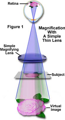
Since the image appears to be on the same side of the lens as the object, it cannot be projected onto a screen. Such images are termed virtual images and they appear upright, not inverted. Figure 1 presents an illustration of how a simple magnifying lens operates. The object (in this case the subject is a rose) is being viewed with a simple bi-convex lens. Light reflected from the rose enters the lens in straight lines as illustrated in Figure 1. This light is refracted and focused by the lens to produce a virtual image on the retina. The image of the rose is magnified because we perceive the actual size of the object (the rose) to be at infinity because our eyes trace the light rays back in straight lines to the virtual image (Figure 1). This is discussed in greater detail below.
Simple Magnification
Explore how a simple magnifying lens operates to increase the perceived size of an object.
When you look into a microscope, you are not looking at the specimen, you are looking at the image of the specimen. The image appears to be "floating" in space about 10 millimeters below the top of the observation tube (at the level of the fixed diaphragm of the eyepiece) where the eyepiece is inserted. The image you observe is not tangible; it cannot be grasped. It is a "map" or representation of the specimen in various colors and/or shades of gray from black to white. The expectation is that the image will be an accurate representation of the specimen; accurate as to detail, shape and color/intensity. The implications are that it may well be possible (and is) to produce highly accurate images. Conversely, it may be (and often is) all too easy to degrade an image through improper technique or poor equipment.
To understand how the microscope's lenses function, you should recall some of the basic principles of lens action in image formation. We will now review several different imaging scenarios using a simple bi-convex lens:
Light from an object that is very far away from the front of a convex lens (we will assume our "object" is the giraffe illustrated in Figure 2) will be brought to a focus at a fixed point behind the lens. This is known as the focal point of the lens. We are all familiar with the idea of a "burning glass" which can focus the essentially parallel rays from the sun to burn a hole in piece of paper. The vertical plane in which the focal point lies is the focal plane.
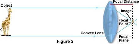
The distance from the center of the convex lens to the focal plane is know as the focal distance. (For an idealized symmetrical thin convex lens, this distance is the same in front of or behind the lens.) The image of our giraffe now appears at the focal plane (as illustrated in Figure 2). The image is smaller than the object (the giraffe); it is inverted and is a real image capable of being captured on film. This is the case for the camera used for ordinary scenic photography.
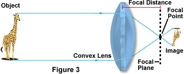
The object is now moved closer to the front of the lens but is still more than two focal lengths in front of the lens (this scenario is addressed in Figure 3). Now, the image is found further behind the lens. It is larger than the one described above, but is still smaller than the object. The image is inverted, and is a real image. This is the case for ordinary portrait photography.
Image Magnification
Explore how the image of the giraffe is magnified by a simple thin bi-convex lens.
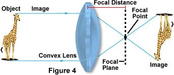
The object is brought to twice the focal distance in front of the lens. The image is now two focal lengths behind the lens as illustrated in Figure 4. It is the same size as the object; it is real and inverted.
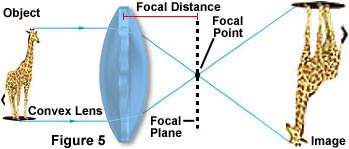
The object is now situated between one and two focal lengths in front of the lens (shown in Figure 5). Now the image is still further away from the back of the lens. This time, the image is magnified and is larger than the object; it is still inverted and it is real. This case describes the functioning of all finite tube length objectives used in microscopy. Such finite tube length objectives project a real, inverted, and magnified image into the body tube of the microscope. This image comes into focus at the plane of the fixed diaphragm in the eyepiece. The distance from the back focal plane of the objective (not necessarily its back lens) to the plane of the fixed diaphragm of the eyepiece is known as the optical tube length of the objective.
In the last case, the object is situated at the front focal plane of the convex lens. In this case, the rays of light emerge from the lens in parallel. The image is located on the same side of the lens as the object, and it appears upright (see Figure 1). The image is a virtual image and appears as if it were 10 inches from the eye, similar to the functioning of a simple magnifying glass; the magnification factor depends on the curvature of the lens.
The last case listed above describes the functioning of the observation eyepiece of the microscope. The "object" examined by the eyepiece is the magnified, inverted, real image projected by the objective. When the human eye is placed above the eyepiece, the lens and cornea of the eye "look" at this secondarily magnified virtual image and see this virtual image as if it were 10 inches from the eye, near the base of the microscope.
This case also describes the functioning of the now widely used infinity-corrected objectives. For such objectives, the object or specimen is positioned at exactly the front focal plane of the objective. Light from such a lens emerges in parallel rays from every azimuth. In order to bring such rays to focus, the microscope body or the binocular observation head must incorporate a tube lens in the light path, between the objective and the eyepiece, designed to bring the image formed by the objective to focus at the plane of the fixed diaphragm of the eyepiece. The magnification of an infinity-corrected objective equals the focal length of the tube lens (for Olympus equipment this is 180mm, Nikon uses a focal length of 200mm; other manufacturers use other focal lengths) divided by the focal length of the objective lens in use. For example, a 10X infinity-corrected objective, in the Olympus series, would have a focal length of 18mm (180mm/10).
Objective Focal Length
Discover how changes in magnification and tube length affect objective focal length.
An easy way to understand the microscope is by means of a comparison with a slide projector, a device familiar to most of us. Visualize a slide projector turned on its end with the lamp housing resting on a table. The light from the bulb passes through a condensing lens, and then through the transparency, and then through the projection lens onto a screen placed at right angles to the beam of light at a given distance from the projection lens. The real image on this screen emerges inverted (upside down and reversed) and magnified. If we were to take away the screen and instead use a magnifying glass to examine the real image in space, we could further enlarge the image, thus producing another or second-stage magnification.
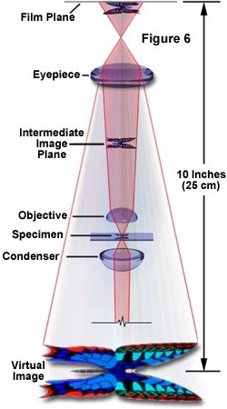
Now we will describe how a microscope works in somewhat more detail. The first lens of a microscope is the one closest to the object being examined and, for this reason, is called the objective. Light from either an external or internal (within the microscope body) source is first passed through the substage condenser, which forms a well-defined light cone that is concentrated onto the object (specimen). Light passes through the specimen and into the objective (similar to the projection lens of the projector described above), which then projects a real, inverted, and magnified image of the specimen to a fixed plane within the microscope that is termed the intermediate image plane (illustrated in Figure 6). The objective has several major functions:
- The objective must gather the light coming from each of the various parts or points of the specimen.
- The objective must have the capacity to reconstitute the light coming from the various points of the specimen into the various corresponding points in the image (Sometimes called anti-points).
- The objective must be constructed so that it will be focused close enough to the specimen so that it will project a magnified, real image up into the body tube.
The intermediate image plane is usually located about 10 millimeters below the top of the microscope body tube at a specific location within the fixed internal diaphragm of the eyepiece. The distance between the back focal plane of the objective and the intermediate image is termed the optical tube length. Note that this value is different from the mechanical tube length of a microscope, which is the distance between the nosepiece (where the objective is mounted) to the top edge of the observation tubes where the eyepieces (oculars) are inserted.
The eyepiece or ocular, which fits into the body tube at the upper end, is the farthest optical component from the specimen. In modern microscopes, the eyepiece is held into place by a shoulder on the top of the microscope observation tube, which keeps it from falling into the tube. The placement of the eyepiece is such that its eye (upper) lens further magnifies the real image projected by the objective. The eye of the observer sees this secondarily magnified image as if it were at a distance of 10 inches (25 centimeters) from the eye; hence this virtual image appears as if it were near the base of the microscope. The distance from the top of the microscope observation tube to the shoulder of the objective (where it fits into the nosepiece) is usually 160 mm in a finite tube length system. This is known as the mechanical tube length as discussed above. The eyepiece has several major functions:
- The eyepiece serves to further magnify the real image projected by the objective.
- In visual observation, the eyepiece produces a secondarily enlarged virtual image.
- In photomicrography, it produces a secondarily enlarged real image projected by the objective. This augmented real image can be projected on the photographic film in a camera or upon a screen held above the eyepiece.
- The eyepiece can be fitted with scales, markers or crosshairs (often referred to as graticules, reticules or reticles) in such a way that the image of these inserts can be superimposed on the image of the specimen.
The factor that determines the amount of image magnification is the objective magnifying power, which is predetermined during construction of the objective optical elements. Objectives typically have magnifying powers that range from 1:1 (1X) to 100:1 (100X), with the most common powers being 4X (or 5X), 10X, 20X, 40X (or 50X), and 100X. An important feature of microscope objectives is their very short focal lengths that allow increased magnification at a given distance when compared to an ordinary hand lens (illustrated in Figure 1). The primary reason that microscopes are so efficient at magnification is the two-stage enlargement that is achieved over such a short optical path, due to the short focal lengths of the optical components.
Eyepieces, like objectives, are classified in terms of their ability to magnify the intermediate image. Their magnification factors vary between 5X and 30X with the most commonly used eyepieces having a value of 10X-15X. Total visual magnification of the microscope is derived by multiplying the magnification values of the objective and the eyepiece. For instance, using a 5X objective with a 10X eyepiece yields a total visual magnification of 50X and likewise, at the top end of the scale, using a 100X objective with a 30X eyepiece gives a visual magnification of 3000X.
Total magnification is also dependent upon the tube length of the microscope. Most standard fixed tube length microscopes have a tube length of 160, 170, 200, or 210 millimeters with 160 millimeters being the most common for transmitted light biomedical microscopes. Many industrial microscopes, designed for use in the semiconductor industry, have a tube length of 210 millimeters. The objectives and eyepieces of these microscopes have optical properties designed for a specific tube length, and using an objective or eyepiece in a microscope of different tube length will lead to changes in the magnification factor (and may also lead to an increase in optical aberration lens errors). Infinity-corrected microscopes also have eyepieces and objectives that are optically-tuned to the design of the microscope, and these should not be interchanged between microscopes with different infinity tube lengths.
Modern research microscopes are very complex and often have both episcopic and diascopic illuminators built into the microscope housing. Design constrictions in these microscopes preclude limiting the tube length to the physical dimension of 160 millimeters resulting the need to compensate for the added physical size of the microscope body and mechanical tube. This is done by the addition of a set of parallelizing lenses to shorten the apparent mechanical tube length of the microscope. These additional lenses will sometimes introduce an additional magnification factor (usually around 1.25-1.5X) that must be taken into account when calculating both the visual and photomicrographic magnification. This additional magnification factor is referred to as a tube factor in the user manuals provided by most microscope manufacturers. Thus, if a 5X objective is being used with a 15X set of eyepieces, then the total visual magnification becomes 93.75X (using a 1.25X tube factor) or 112.5X (using a 1.5X tube factor).
In addition to the parallelizing lenses used in some microscopes, manufacturers may also provide additional lenses (sometimes called magnification changers) that can be rotated into the optical pathway to increase the magnification factor. This is often done to provide ease in specimen framing for photomicrography. These lenses usually have very small magnification factors ranging from 1.25X up to 2.5X, but use of these lenses may lead to empty magnification, a situation where the image is enlarged, but no additional detail is resolved. This type of error is illustrated in Figure 7 with photomicrographs of liquid crystalline DNA. The photomicrograph in Figure 7(a) was taken with a 20X plan achromat objective under polarized light with a numerical aperture of 0.40 and photographically enlarged by a factor of 10X. Detail is crisp and focus is sharp in this photomicrograph that reveals many structural details about this hexagonally-packed liquid crystalline polymer. Conversely, the photomicrograph on the right (Figure 7(b)) was taken with a 4X plan achromat objective, having a numerical aperture of 0.10 and photographically enlarged by a factor of 50X. This photomicrograph lacks the detail and clarity present in Figure 7(a) and demonstrates a significant lack of resolution caused by the empty magnification factor introduced by the enormous degree of enlargement.
Care should be taken in choosing eyepiece/objective combinations to ensure the optimal magnification of specimen detail without adding unnecessary artifacts. For instance, to achieve a magnification of 250X, the microscopist could choose a 25X eyepiece coupled to a 10X objective. An alternative choice for the same magnification would be a 10X eyepiece with a 25X objective. Because the 25X objective has a higher numerical aperture (approximately 0.65) than does the 10X objective (approximately 0.25), and considering that numerical aperture values define an objective's resolution, it is clear that the latter choice would be the best. If photomicrographs of the same viewfield were made with each objective/eyepiece combination described above, it would be obvious that the 10x eyepiece/25x objective duo would produce photomicrographs that excelled in specimen detail and clarity when compared to the alternative combination.
The range of useful total magnification for an objective/eyepiece combination is defined by the numerical aperture of the system. There is a minimum magnification necessary for the detail present in an image to be resolved, and this value is usually rather arbitrarily set as 500 times the numerical aperture (500 × NA). At the other end of the spectrum, the maximum useful magnification of an image is usually set at 1000 times the numerical aperture (1000 × NA). Magnifications higher than this value will yield no further useful information or finer resolution of image detail, and will usually lead to image degradation, as discussed above. Exceeding the limit of useful magnification causes the image to suffer from the phenomenon of empty magnification (see Figures 7 (a) and (b)), where increasing magnification through the eyepiece or intermediate tube lens only causes the image to become more magnified with no corresponding increase in detail resolution. Table 1 lists the common objective/eyepiece combinations that lie in the range of useful magnification.
Range of Useful Magnification
(500-1000 × NA of Objective)
| OBJECTIVE (NA) | EYEPIECES | ||||
| 10x | 12.5x | 15x | 20x | 25x | |
| 2.5X (0.08) | --- | --- | --- | x | x |
| 4X (0.12) | --- | --- | x | x | x |
| 10X (0.35) | x | x | x | x | x |
| 25X (0.55) | x | x | x | x | --- |
| 40X (0.70) | x | x | x | --- | --- |
| 60X (0.95) | x | x | x | --- | --- |
| 100X (1.40) | x | x | --- | --- | --- |
| x = good combination | |||||
Table 1
These basic principles underlie the operation and construction of the compound microscope which, unlike a magnifying glass or simple microscope, employs a group of lenses aligned in series. The elaboration of these principles has led to the development, over the past several hundred years, of today's sophisticated instruments. Modern microscopes are often modular with interchangeable parts for different purposes; such microscopes are capable of producing images from low to high magnification with remarkable clarity and contrast.