Capturing images observed in the microscope onto the emulsion of photographic film or into the pixel array of a charge-coupled device (CCD) allows scientists to produce a "hard copy" for research records and publication. In photomicrography, regular camera lenses are not used because the microscope optical train, from the light source to the photoeyepiece, constitutes the image-forming lens assembly and illumination system.
The camera body itself has the function protecting the film in a light-tight compartment and correctly positioning the film within the focal plane for exposure, then advancing the film roll one frame at a time after each new photomicrograph is recorded. Photomicrographic equipment ranges from the comparatively simple point-and-shoot camera with an integral lens to sophisticated light-metering camera systems capable of accurately measuring exposures and automatically compensating for artifacts such as reciprocity failure and dense filtration.
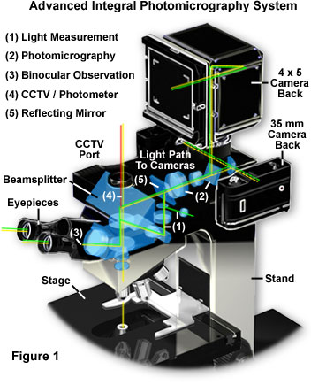
Modern microscopes with integral camera systems offer a significant advantage to the microscopist in the ability to control the light path through the microscope. Presented in Figure 1 is a complex state-of-the-art advanced automatic exposure photomicrography system, typical of that found on high-end contemporary reasearch microscopes. The microscope illustrated in Figure 1 is designed with a sliding mirror system, in which the image formed by the objective lens is projected directly onto the film plane rather than being relayed through a series of lenses. This reduces the number of lenses and reflecting surfaces in the optical pathway and results in the fastest possible shutter speeds, minimizing the effects of vibration and stage drift. In addition, reciprocity and exposure errors are reduced or even eliminated by the advanced exposure measurement system with built-in reciprocity compensation.
To review the optical train of the microscope illustrated in Figure 1, the light is first focused on the specimen before being captured by the objective lens and directed to a beamsplitter located in the body between the nosepiece and the binocular eyepiece housing. A set of adjustment sliders allows the microscopist to select the light path direction through the microscope, shown in the drawing as a series of green lines. For normal observation, the microscopist can select the binocular observation mode (noted by the white numeral (3) in the pathway) that employs the basic optical system of the microscope with no light loss. When the light measurement mode is selected, light from the measurement area alone is directed to a photomultiplier (light pathway; (1)), enabling bright image observation for the non-measured area. The microscopist can directly confirm the measurement area and observe the exact image to be photographed for more accurate composition. In photography mode (light pathway; (2)), the reflecting mirror (light pathway; (5)) slides out when the exposure button is depressed, allowing 100 percent of the light to reach the film emulsion. This reduces the influence of stray light and enables the fastest shutter speeds possible, with full utilization of the objective lens aperture at minimum light noise levels. When the microscope is coupled to a CCD digital still or video camera (TV/Photometer mode; (4)), 100 percent of the light is directed to a port containing a C-mount adapter, allowing video capture without light loss for image analysis, quantitative analysis, and photomicrography of dark or fluorescence specimens.
All of the major microscope manufacturers offer high-end microscopes with integrated camera systems such as the one illustrated in Figure 1. Olympus markets the Provis AX series of automatic research photomicroscopes, while Nikon offers the Eclipse 1000 series microscopes, both of which have all of the features described above. Leica and Zeiss produce the DAS Mikroskop and Axiophot, respectively. All four of these microscopes can be controlled with an accompanying computer through serial port connections built into the microscope body. The advanced research microscopes manufactured by these companies represent the most sophisticated optical microscopes ever marketed to the scientific community. Many of the specialized features exhibited by microscopes of this type will be discussed more thoroughly below.
Not all microscopists can afford the luxury of an automatic microscope photography system and most are forced to settle for a simpler configuration. If the microscope in use is not equipped with a photomicrography system, it can be readily adapted to almost any camera available to the microscopist. The simplest configuration is a compact view camera having an integral lens system, such as is illustrated in Figure 2. This system centers around a point and shoot camera (or even a lens in a box, commonly offered in drugstores and supermarkets) that has been coupled to the microscope eyepiece for photomicrography. The lower end cameras in this class contain a fixed-focus integral lens having a single shutter speed and fixed aperture. Furthermore, many modern compact cameras have a shutter mechanism operated by an external light meter that does not have a manual override, precluding their use with an optical microscope. More expensive cameras have several shutter speeds, the ability to change exposure with a built-in light metering device, and two or more aperture settings.
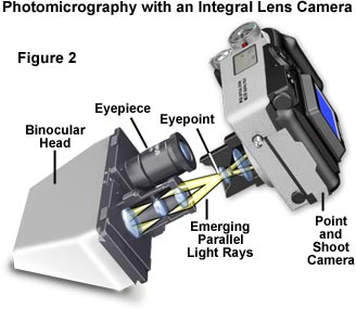
A scarcity of adapters is available for coupling a fixed-lens camera to the microscope eyepiece, and in most instances, some improvisation is necessary to successfully adapt the camera to the microscope. The camera should be set for infinity focus (the default in most cameras of this type) and positioned so that the front surface of the integral lens rests at the eyepoint of the eyepiece (that has an image focused at minus infinity), concentric with the microscope optical axis and allowing the image to be focused on the film plane. Adapting the camera to the microscope eyepiece is the most difficult aspect of this configuration. Because there are a wide spectrum of camera designs available, it is virtually impossible to obtain an aftermarket coupling device to attach the camera to a microscope. Instead, the microscopist can use a ring stand, camera tripod, copystand, or other support bracket to secure the camera into position. Entry of stray light into the junction of the microscope/camera system should be minimized by using a coupling that is light-tight (or as much so as possible).
Recently, Olympus and Nikon have introduced adapters designed to attach their integral lens digital cameras (CookPix (Nikon) and C2020/C3030 (Olympus)) to the trinocular camera tube of a microscope. It should also be possible to use one of these adapters (possibly with some small degree of modification) to connect integral-lens 35 millimeter film cameras to a microscope. An eyepiece is inserted inside the camera tube of the trinocular head and the adapter is fitted into the tube. A small thumbscrew secures the camera lens inside the bracket with the front lens resting at the eyepoint of the eyepiece. The exact location of the eyepoint can be determined by holding a piece of white or frosted paper just above the eyelens with the microscope turned on and focused. A bright circle of light will be projected by the eyepiece onto the paper's surface, which can be moved upward and downward to make the circle larger or smaller. The position where the light circle is smallest is the eyepoint, and this is where the front lens surface of the camera should reside.
If the point and shoot camera has adjustable aperture settings, set the aperture to the largest value available to minimize vignetting of the image. The camera aperture setting does not control image intensity or exposure times and will only serve to reduce the illumination at the edge of the view field. At the lowest aperture setting, the diaphragm will severely restrict the image field size so that only a small circular image is recorded in the center of the film. Even at the largest aperture setting, vignetting is unavoidable and will occur to some degree. The biggest problem with adapting point and shoot cameras to a microscope is the very fast shutter speeds (1/25 to 1/50 second) utilized by these popular cameras. Unless the amount of light projected into the eyepieces is great enough, images will be dark. Always set the microscope illumination intensity to the highest available position when using cameras of this type.
Among the greatest disadvantages to using integral lens cameras with the microscope is the small field size recorded on film, usually occupying only about half of the available area. Often the peripheral area of the photomicrograph is out of focus due to lens aberrations both in the microscope and with the camera lens system. If possible, use the widest angle camera lens available, such as an 80 millimeter, rather than a 28, 35 or 50 millimeter lens. Using the highest possible magnification eyepieces can also help to reduce this effect, but it usually can not be eliminated. Reflections (which seriously affect specimen contrast) from multiple lens elements present in the camera can also produce bright spots in photomicrographs taken with these cameras. The simpler the camera lens system, the better the quality of photomicrographs.
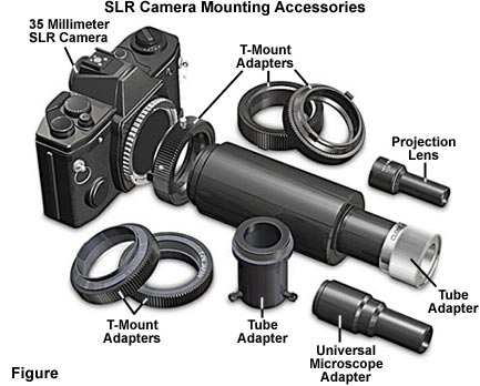
For microscopists who own a 35 millimeter single lens reflex (SLR) camera, adapting the camera to the microscope is more straight forward. The 35 millimeter film format is the most popular, and a wide range of accessories and aftermarket products exist for these camera systems. The equipment necessary to adapt the camera to a microscope consists of a hollow cylindrical extension or phototube (labeled tube adapter in Figure 3), the lower end of which fastens to the straight tube of the trinocular microscope observation head, or to a modified intermediate piece that replaces the observation head (Figure 3). At the upper part of the phototube is a T-mount adapter, which is threaded onto the tube and has a bayonet mount that receives a SLR camera whose camera lens has been removed. The entire assembly is called an L adapter and is marketed by a number of distributors. T-mount adapters to fit most popular camera bodies are also available.
Many SLR cameras have a built-in silicon blue type exposure meter for automatically measuring light and controlling the opening and closing of the built-in camera shutter. These devices work well if the exposure is not longer than several seconds or shorter than 1/3 second. They may suffer from blurring of the picture because of the "bounce" of the built-in focal plane shutter and/or the raising of the built-in auto-return mirror prior to the opening of the shutter. With SLR cameras, a mirror behind the lens reflects an image onto a ground glass screen that is positioned at the same distance from the lens as the film plane. The image projected onto the screen is inverted by a pentaprism to yield an erect, laterally correct image that can be focused by viewing the magnified screen. When the camera shutter release is activated, the mirror swings out of the light path and the shutter opens to allow light to expose the film emulsion. After the specified exposure time, the shutter closes and the mirror swings back into position allowing the photographer to compose the next frame. Exposure is usually determined by an integral metering system that measures light through-the-lens (TTL) directly on the ground glass screen. An alternative metering method, termed off-the-film (OTF), involves recording exposure values based on the amount of light reflected from the film surface during exposure. Be cautious when adapting a modern autofocus camera to a microscope using a T-mount adapter, because some cameras require an autofocus lens to be in place before the metering and exposure systems will activate. These cameras consider a microscope adapter to be a manual focus lens and behave accordingly.
For easier focusing, the viewing screen of a SLR camera should be replaced with a ground glass or equivalent screen having crosshairs and a clear central circular area. Modern focusing screens are laser-cut to provide a better surface than older ground glass materials, and allow the visualization of finer specimen detail, especially at lower magnifications. The Nikon type M screen features a clear Fresnel lens with focusing lines and provides an excellent surface for finding focus, as does the type C matte screens, which have a matte surface with a clear central area and crosshairs. An attachable right angle magnifier is also a valuable accessory. To set up the camera, a photoeyepiece is inserted in the straight tube of the trinocular head, the L adapter is tightened in place, and the camera body loaded with film is attached to the upper end of the L adapter. The microscope image is visible on the camera viewing screen and the shutter button, preferably with a cable release, can be pressed to capture a photomicrograph.
SLR cameras usually have either a focal-plane shutter or leaf shutter mechanism, both of which are reliable, but the leaf shutter is symmetrical with light-weight moving parts and produces less vibration during shutter activation. This type of shutter is preferred over the focal-plane type and should be considered when purchasing a 35 millimeter SLR camera for photomicrography. The internal mirror in a SLR camera is a source of significant vibration when it swings out of the way during the exposure sequence. Some of the more advanced cameras have a mirror pre-release system that swings the mirror up before the shutter mechanism is activated to reduce or eliminate vibration errors in photomicrography.
The image produced by a microscope eyepiece is a virtual image formed at infinity, and cannot be captured on a screen, CCD, or film emulsion surface. Parallel light rays emerging from the eyepiece are focused by the lens of the eye onto the retina for transmission to and interpretation by the brain. To form a real image that can be projected onto the film plane, the distance between the objective and specimen is often changed. Focus on the camera film plane can be adjusted using the microscope rack to move the specimen up or down on the stage. In some cases, the eyepiece position should be changed to place the image formed by the objective beyond the focal point of the eyepiece. This will avoid spherical and field curvature aberrations caused by changing the objective focus position after the microscope has been visually focused. Alternative methods of forming a projected image involve the use of a specially designed photoeyepiece (projection lens) designed for short projection distances (approximately 125 millimeters) between the eyepiece exit pupil and the camera film plane. This projection distance truncates that normally required for visual conditions using standard eyepieces, which have an infinite projection distance. Projection lenses used in photomicrography typically have useful magnification factors of 2.5x to 3.3x, although higher magnifications (up to 7x) are available for special circumstances.
One of the major problems with using a SLR camera at high magnifications is the difficulty encountered in focusing the image on the ground glass screen positioned within the camera viewfinder. At magnifications higher than 100x, critical focus of fine detail becomes almost impossible because the screen surface is too rough. The best solution is to utilize a specially designed glass or plastic screen that has a clear area in the center with a pair of crosshairs for focusing, as discussed above. These are available from the camera manufacturers and aftermarket product distributors.
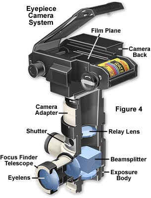
The next step up is a manual photomicrographic camera (the generic name for such a camera is "eyepiece camera" or attachment camera), which is illustrated in Figure 4. This camera system accepts a manual 35mm film back or an adapter for standard medium format (3¼" × 4¼") Polaroid film or large format (up to 4" × 5") Polaroid or sheet film. These camera systems have the advantage of using a leaf-type shutter (mounted in a vibration-free rubber mounting and set by hand) but they usually do not have a built-in exposure meter. Exposures must be determined by running trial and error tests or using an optional attachable exposure metering device. The camera also has an attachable focusing telescope with built-in crosshairs, mounted parallel to the table top, thus making focusing of the image more convenient. Images in the microscope can be viewed, focused, and photomicrographs composed while viewing the specimen through the focusing telescope (without need of the binocular eyepieces). Most telescopes have built-in reticles that contain a rectangular grid and crosshairs for adjusting the parfocality between the telescope and camera film plane. The portion of the specimen that will be imaged on film appears within the confines of the grid, which is useful in composing photomicrographs.
Camera systems of this type require a photoeyepiece, which is positioned in the microscope head just above the intermediate tube (if so equipped) and beneath the exposure body of the camera tube. The photoeyepiece magnification factor determines the size of the image projected onto the film plane and should be compatible with the diagonal dimensions of the film frame to avoid vignetting of photomicrographs. Photoeyepiece magnification factors of 2.5x to 3.3x are useful for this camera system. The distance between the eyepoint ranges between 100 and 150 millimeters, which is significantly less than 250 millimeters (the normal close focus distance of the human eye), necessitating the use of a correcting lens to compensate for microscope tube length and to allow parfocalization between the viewing telescope and the film plane.
Photomask Reticle Operation
Practice adjustment of the photomask reticle mounted in a focusing eyepiece using this interactive tutorial.
Focusing the viewfinder (viewing telescope) is critical in achieving sharp and crisp photomicrographs. The crosshairs of the viewing telescope should be placed in focus before the specimen is viewed so that minute details in specimen structure do not confuse the correct focus of the viewfinder. Remove any specimens from the microscope stage and adjust the illumination so a blank field is visible in the viewing telescope with no specimen present. Next, peer through the viewing telescope and rotate the outer housing until the reticle is brought into focus. Place a specimen on the stage and bring it into focus using the microscope focusing rack while observing through the viewing telescope. After both the reticle and specimen are in simultaneous focus, the eyepiece camera is ready for photomicrography.
Be cautious when framing and focusing specimens using low power (1x, 2x, and 4x) objectives, which are very difficult to use due to the very shallow depth of focus at the camera film or image plane. Objectives in this magnification range have focus depths ranging from 0.03 to 1.4 microns as opposed to higher power 20x and 40x objectives, which have focus depths of 4.75 and 12.0 microns, respectively. Small errors in focusing the low power objectives often lead to photomicrographs with focus problems, which does not happen as often in higher power objectives in which the focus depth is substantially greater. The focus errors can be overcome by using a low power (4x) auxiliary focus finder (stand-alone telescope) to assist in finding focus. These are available through all of the microscope manufacturers as accessories. To use the focus finder, first focus on a distant object (for example, an object outside the window), then place the focused telescope over the viewfinder and twist the knurled eyelens mount until the reticle crosshairs are brought into sharp focus. Next, adjust the microscope coarse and fine focusing knobs until the specimen appears in focus and superimposed over the focused reticle. To check focus of the specimen using the parallax method, move the head to the left and right of the viewfinder to ensure the relative positions of the specimen and crosshairs remains fixed and do not appear to move relative to one another.
Many commercial eyepiece camera systems have interchangeable film backs to allow the use of larger format (up to 4" × 5") Polaroid and sheet film. Large format films circumvent empty magnification problems that sometimes occur with smaller 35 millimeter film formats during enlargement. Some camera systems are equipped with a beamsplitter that divides the light between the film plane and the viewing telescope. When positioned in the optical pathway, the beamsplitter directs a small percentage of the light (usually 25-40 percent) to the viewfinder, decreasing the amount of light available to expose the film emulsion. If the camera is equipped with a moveable beamsplitter, then it should be removed from the light path (either manually or automatically to coincide with shutter operation) prior to making an exposure on film.
The visual magnification of an optical microscope is determined by the product of the magnification of the objective, the eyepieces, and any intermediate lenses in the optical train. In a similar manner, the photographic magnification displayed by film recorded by a microscope is a product of the microscope magnification factor (objective plus projection lens) and the magnification factor of the camera. When using a fixed lens or SLR camera with a microscope, the actual magnification recorded on film can be easily measured by means of a stage micrometer. Place the micrometer on the microscope stage, focus on an area containing ruled parallel lines of known separation distance, and capture a photomicrograph with the camera. After processing the film, measure the distance between two successive lines and compare this distance to the known size of the line divisions. For example, if the micrometer line spacing is 10 microns (a commonly used size) and the measured distance between lines on the photomicrograph is 2.25 millimeters, then the magnification is (2.25 divided by 0.01) 225x on the photograph.
Most larger format cameras used in microscopy (3¼" × 4¼" and 4" × 5") have a magnification factor ranging between 0.75x and 1.25x, a number that is usually inscribed on the camera back. Some of the newer large format film camera backs have higher magnifications, in the neighborhood of 3x or 4x, when used with modern low magnification projection lenses. The majority of 35 millimeter cameras for photomicrography have a magnification factor ranging between 0.25x and 0.5x, much smaller than that of the larger format cameras. Multiplying the magnification factors of the optical components in the microscope and camera system will provide the final magnification on film. For instance, a 40x objective used with a 2.5x projection lens and a camera magnification factor of 2x will yield a magnification of 200x on the actual film itself.
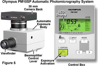
Next in the hierarchy of sophistication is an entry-level research automatic camera system, offered by all of the major microscope manufacturers, of which the Olympus PM-10SP (Figure 5) is an excellent example. This camera has a vibration-free electronic shutter and accepts both 35mm camera backs and large format adapters. The automatic exposure body is equipped with a focusing telescope and a built-in silicon blue exposure meter, reading the central 30 percent of the field of view and automatically controlling the opening and closing of the shutter. A spot meter that measures light intensity over one percent of the viewfield (the central portion) is also provided to assist with exposure determination in fields that have either bright specimens on a dark background or visa versa. The separate control unit is compact and works very well for most modes of microscopy, with the exception of fluorescence. The actual exposure is displayed on a liquid crystal (LCD) screen indicating the approximate duration of the exposure. One of the 35mm camera backs permits automatic winding of the film after each exposure is made. A photoeyepiece is required to project the image formed in the microscope onto the film.
Almost all modern automatic camera systems are equipped with a viewfinder housed in the exposure body, which allows the microscopist to view and focus an aerial image of the specimen prior to recording the image on film. A useful option, available as an accessory on most microscopes, is an auxiliary binocular focus finder eyepiece reticle that can be used to focus and compose photomicrographs. The binocular eyepiece reticle is operated in the same manner as an exposure body eyepiece reticle. The focusing eyelens of the eyepiece is used to achieve sharp focus of a crosshair set positioned in the center of the reticle, then the specimen is focused using the microscope coarse and fine focusing knobs. The reticle has markings that delineate the diagonal size of the image projected onto the film frame with separate markings for each of the projection lenses available for the system. In addition, another set of markings specifies the image area projected onto the film plane for each of the various film formats compatible with the camera back. If the microscope is equipped with both a binocular eyepiece reticle and a viewfinder reticle, then it is important to ensure both eyepieces are parfocal. The orientation of the binocular eyepiece reticle is important because the field of view perspective seen from these eyepieces is independent the one projected into the camera viewfinder, which actually represents the exact area of the image captured on film. If the camera system is twisted slightly to the left or right of center, then the two viewfields will not be the same. In this case, photomicrographs composed using the binocular eyepieces will not represent the true boundaries of the image as they appear on film. The axial orientation of the binocular eyepiece with respect to the eyepiece tube is also critical. Most eyepieces equipped with a reticle also have a setscrew that secures the orientation of the eyepiece (and reticle) within a slot in the tube. If the screw is not correctly positioned in the slot, then the eyepiece will not be properly seated (no longer conjugate to the image plane) and will have a skewed axial orientation.
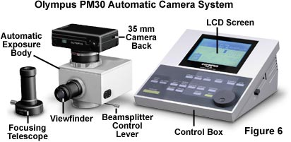
Even more sophisticated automatic camera systems are available for high-end research microscopes. Olympus markets two camera models, the PM-20 and the PM-30, that offer more features than the simpler PM-10SC and are capable of being used with Olympus and other makes of microscopes (Figure 6). Both exposure bodies mount 35 millimeter film backs that are fully automatic and have autoload, autowind and autorewind functions. Data recording backs are also available that will imprint information such as the date, time, temperature, operator name, and other photographic data directly onto the film emulsion. Both camera systems accept a large film format adapter for a 3¼" × 4¼" Polaroid film pack or 4" × 5" cut sheet film or Polaroid film, including a data back for large format (3¼" × 4¼" film pack) imprinting. The exposure bodies have a mount for a focusing telescope with built-in crosshairs and target, parfocal with the film plane, for accurate focusing.
The control panel of both units has a liquid crystal display that permits user-controlled entry for such items as film size, ISO rating of film, exposure adjust for unusual lighting conditions, reciprocity setting, automatic ISO setting for DX coded film, double exposure capability, exposure lock, bracketing exposure settings, color temperature accessory, lighted frame for fluorescence, and several other variables. The PM-20 has a built-in silicon photodiode system whose meter reads the central 30 percent of the field of view or, using the spot meter lever, the central 1 percent of the field of view. The automatic exposure meter reads the "live" image continuously until the shutter closes. The PM-20 has a setting for fluorescence microscopy whose algorithm automatically reduces the exposure time by 80 percent to prevent overexposure.
Illuminated Reticles
Examine the advantage that illuminated reticles have on the ability to visualize and frame weakly fluorescent and dark specimens.
Start Tutorial »The PM-30 has a metering system consisting of an array of 400 CCD (charge-coupled device) elements. This device reads the light in the central 30 percent of the field of view or can be set to spot read the central 1 percent or 0.1 percent of the field of view. The CCD device is very sensitive, even under low light conditions, and is thus extremely useful for fluorescence micrography. Both the PM-20 and PM-30 it can be set for Fl or SuperFl fluorescence photomicrography modes. The metering system on the PM-30 reads the exposure time up until the pressing of the exposure button. When the exposure button is depressed, the prism diverting the light to the focusing telescope swings out of the light path permitting 100 percent of the light coming up the straight tube of the trinocular to reach the film plane. This feature increases the amount of light reaching the film emulsion while simultaneously decreasing exposure time and ensuring that scattered room light does not enter the focusing telescope to be projected onto the film. Both cameras have memory capability, however the PM-30 accepts memory data cards and also has an RS232 port for external communications and control by a peripheral computer. Standard 2.5x and 3.3x projection lenses are used to image specimen with both systems.
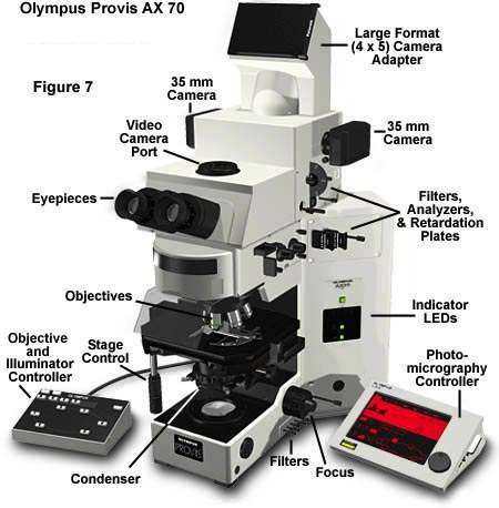
Finally, the large AX-70 and 80 Provis research microscopes have a U-Photo Camera system (Figure 7), which has much the same capabilities as the PM-30, but this system has a built-in focusing magnifier as well as a user-moveable, blinking spot metering device that can be moved to meter any part of the specimen within the central 30 percent of the field of view instead of at the exact center only. A zooming photoeyepiece is built into the U-Photo, ranging from 2.5X to 5X eyepiece magnification on 35mm film or 7.5X-15X on large format film.