Adjustment of a transmitted light microscope for Köhler illumination is a logical and relatively easy process that should be practiced until mastered by all serious students of microscopy. Each time a microscope is turned on, it should be carefully inspected to ensure proper alignment of all optical components, and to guarantee that the lamp is centered and the condenser and field diaphragm are properly adjusted for Köhler illumination.
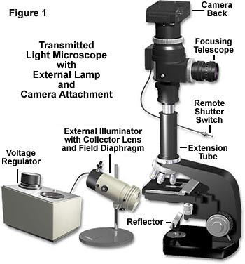
The microscope illustrated in Figure 1 uses an advanced external light source to provide illumination for the microscope. The lamp housing contains both a field diaphragm and collector lens, in addition to a tungsten-halogen bulb. A separate voltage regulator provides an adjustable direct-current voltage source for the lamp that varies between 5 and 12 volts. Modern microscopes usually contain a light source built into the base of the microscope, along with the collector lens and field diaphragm. Adjustment of microscopes with either internal or external light sources for Köhler illumination is similar in theory, however there are certain differences in the procedures that will be described below.
An important step in alignment of the microscope, whether it is for Köhler, Nelsonian, or any other strategy for illumination, is alignment of the light source (usually a tungsten-halogen bulb). Many modern microscopes now have pre-centered and pre-focused lamps, but older models still require the light source to be centered and focused by the user. We suggest consulting the owner's manual for instructions about how the lamp is to be centered and for other important information about the illumination source. The following procedures are recommended for aligning both external and internal lamps:
Internal Tungsten-Halogen Lamps
- After switching on the lamp of the microscope, fully open both the field diaphragm (usually near the light port of the microscope) and the condenser aperture diaphragm (controlled by a collar or handle on the substage condenser housing).
- Some manufacturers provide a frosted glass filter for diffusing light emitted from the bulb. This filter is usually located in a filter holder adjacent to the lamp housing where it is attached to the body of the microscope. Remove this filter before proceeding with lamp alignment.
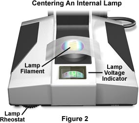
- Place a sheet of white paper, frosted glass, Kim-wipe, or lens-cleaning tissue on the microscope port and the image of the filament will be clearly visible as illustrated in Figure 2.
- Use the adjustment screws on the lamp housing to rotate the lamp (thus, the filament) in its holder and also to move it back and forth or up and down. We have constructed an interactive Java tutorial that reviews the basics of filament alignment. Correctly manipulating the combination of lamp housing adjustments should ensure that the lamp filament is centered in the optical pathway and is focused in the aperture diaphragm of the substage condenser.
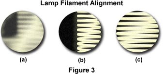
Figure 3 illustrates a typical view of the microscope light port when the filament is made visible using the procedures outlined above. The port on the left in Figure 3(a) contains a filament that is severely out of alignment and not positioned properly to focus an image that will completely fill the aperture diaphragm nor the back focal plane of the objective. Using translational adjustments on the lamp housing, the filament is brought into focus (Figure 3(b)) and then centered within the light port (Figure 3(c)). Visitors and students can practice aligning a "virtual" lamp filament using the interactive Java tutorial below:
Lamp Filament Alignment
Use this tutorial to practice lamp filament alignment while monitoring the filament both in the microscope port and at the back focal plane of the objective.
External Tungsten and Tungsten-Halogen Lamps
- Most external light sources are older and do not have pre-centered bulbs. The first step in centering an external tungsten-halogen lamp is to project an image of the filament onto a distant sheet of paper, supported by a book or the wall. Use the adjustment screws or knobs to rotate the filament about its own axis and ensure that it is centered within the optical axis of the condenser lens and field diaphragm, which are an integral part of the external illumination source.
- Place the external illuminator about 7-10 inches away from the reflector mirror located on the base of the microscope directly beneath the substage condenser (see Figure 1). Many of the mirrors on microscopes designed for external light sources are plano-concave and have one flat (planar) and one concave side. Be certain that the light source is reflecting from the flat surface of the mirror when using an external tungsten-halogen light source.
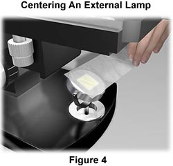
- The lamp filament should be centered in the mirror as illustrated in Figure 4. This can be checked in a manner analogous to the internal lamp by placing a piece of tissue paper over the mirror and visualizing where the filament image is projected. Make any adjustments necessary to bring the external illuminator in line with the microscope optical axis. After centering of the filament, the mirror should be positioned to project the reflection into the substage condenser. Check this by placing a piece of tissue paper over the stage opening. The filament should be out of focus, but framed squarely in the center of the stage opening.
Alignment of the Condenser and Field Diaphragm
- Rotate the nosepiece to bring the 10x objective into the light path. Next, place the specimen on the microscope stage and focus the microscope using the coarse and fine focusing knobs. This should be done by slowly raising the microscope stage while viewing the slide until it is very close to (but not touching!) the objective. At this point, the stage will have to be lowered slightly to bring the specimen into focus. This is an important concept which, when carried out properly, will avoid a collision between the objective and the specimen coverslip. Look through the eyepieces and slowly lower the stage, using the fine focus knob, until specimen details come into focus. The specimen should possess ample contrast and provide a sharp and crisp image. A highly stained biological tissue sample is excellent for aligning the microscope in brightfield mode, however optically birefringent samples can also be used when the microscope is equipped for polarized light or differential interference contrast.
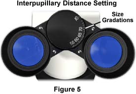
- On binocular microscopes, adjust the eye tubes to coincide with your interpupillary distance. The single fused image should be visible through both eyes without significant movement of the head, and viewing should be comfortable. If only one person uses the microscope, this adjustment should not have to be made very often. Many binocular heads have a graded scale (Figure 5) that corresponds to the size of the interpupillary distance, allowing the microscopist to quickly adjust the eye tubes without viewing through them (the average interpupillary distance is 65 millimeters).
- On modern microscopes, the eye tubes are adjusted in a manner similar to a pair of binoculars. However, on many older models, the eye tubes slide back and forth in a single plane and adjusting them may involve slight changes to the microscope tube length. Regardless of the translation mechanism, the tubes should be positioned at a distance that allows comfortable viewing. Next, rotate the eye lens of the eyepiece that contains the graduated rule or photomicrography until markings on the reticle appear in sharp focus superimposed over a focused specimen. If no reticle is present, rotate the eye lens until the specimen is in focus.
- Diopter adjustment should be made to the eyepieces individually. Some microscopes have a graded scale on each eyepiece that indicates the position of the eyelens with respect to main body of the eyepiece. Other models hold the body of the eyepiece in a fixed position securely in the eye tube with a pin and slot. The first step is to either line up the graded markings on eyepieces equipped with such markings or turn the eye lenses clockwise to the shortest focal length position. Next, focus the specimen with the 10x objective and then rotate the nosepiece until a lower magnification objective (usually the 5x) is above the specimen. At this point, refocus each eye lens individually (do not use the microscope coarse or fine focus mechanisms) until the specimen is in sharp focus. Rotate the 20x objective into the optical path and refocus the microscope with the fine focus knob. Repeat the diopter eye lens adjustments with the 5x objective (again not disturbing the microscope fine focus mechanism), and the microscope should be adjusted to the correct diopter settings. These settings will vary from user to user, so record the position of the eye lenses if the eyepiece has a graded scale for quick return to the proper adjustment.
- Correct diopter adjustment allows for compensation between any differences in the user's left and right eye, so that the entire field of view appears in sharp focus through both eyepieces. This also enables the microscope to remain parfocal through all the different objectives in the nosepiece. Eyepiece diopter adjustment can also offset common vision problems, such as far or near sightedness, allowing the user to view specimens without eyeglasses. However, these eyepiece adjustments will not compensate for astigmatism, forcing users with this eye defect to wear their eyeglasses when examining specimens.
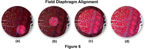
- The next step is to slowly close the field diaphragm (the adjustment is either on the external lamp housing or at the base of the microscope near the light port) to its smallest setting until only a fuzzy outline shows in the viewfield (Figure 6(a)). The substage condenser is mounted on a rack that is (usually) controlled by a knurled knob for up and down movement with respect to the stage. Adjust this knob until the leaves of the field diaphragm are in sharp focus on top of the already-focused specimen, and then use the condenser centering screws to move the image of the field diaphragm to the center of the viewfield (and the optical axis of the microscope - Figure 6(b)).
- When raising or lowering the condenser to focus the leaves of the field diaphragm, the focused image of the diaphragm may have a red or blue halo surrounding the leaves. This is due to a lack of correction for chromatic aberration in the condenser. A condenser having good correction will yield a very sharp outline of the diaphragm with little or no color. The field diaphragm is now opened until about three-quarters of the viewfield is visible and the condenser is then refocused (Figure 6(c)). Check alignment of the condenser and re-adjust if necessary. Now open the field diaphragm until it is just beyond the field of view (for observation), or in the case of photomicrography, just beyond the reticle markings that define the area captured on film. Opening the field diaphragm any farther is unnecessary and will cause excessive glare and a loss of contrast.
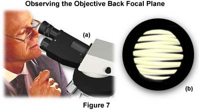
- The next step is to remove one of the eyepieces and peer down the tube of the microscope as shown in Figure 7(a). As you view down the tube, open and close the condenser aperture diaphragm to see its image at the back focal plane of the objective. If there is a frosted diffuser filter built into the light path in the base of the microscope, an evenly lighted circle of light will be visible. If there is no such filter in the light path, you will instead see an image of the lamp filament as, illustrated in Figure 7(b) (a centering or phase telescope inserted in place of the removed eyepiece, or a Bertrand lens will make this adjustment easier to see).
- The purpose of this maneuver is to set the size of the aperture diaphragm to maximize image contrast and to obtain the best possible image of the specimen without introducing a loss of resolution due to refraction and diffraction artifacts. A general rule of thumb is to set the aperture diaphragm between 60 and 90 percent of the size of the entire light disc seen in the eyepiece tube.
Substage Condenser Alignment
This tutorial allows the student to practice alignment and positioning of the substage condenser in the optical pathway to establish Köhler illumination.
Aperture Diaphragm Adjustment
Explore how the size of the condenser aperture diaphragm affects specimen contrast and image quality.
In some instances the edge of the partially closed aperture diaphragm is not concentric with the illuminated back focal plane of the objective. This is due either to a misalignment of the substage condenser or the objective, and the manufacturer's instruction manual should be consulted for the correct centering regime. Some microscopes are shipped with the aperture diaphragm in a fixed and centered position that is impossible to change in the laboratory. Darkfield and phase contrast condensers usually always will provide a centering mechanism due to the crucial aspect of this step in setting up microscopes for these illumination methods. The condenser aperture should be centered with a 40x or 60x objective to avoid having to re-center the diaphragm with each objective (lower power objectives will almost always fall within acceptable margins using this method).
Now that Köhler illumination has been established with the 10x objective, it must be borne in mind that changing to a higher power objective will require a re-alignment of both the field and aperture diaphragms. For example, if you switch to the 40x objective, you will have to close the field diaphragm somewhat and re-center it (looking at a smaller area of the specimen). Also, the condenser aperture diaphragm should be opened slightly (the 40x objective has a higher numerical aperture than does the 10x objective). Each time an objective is changed, both diaphragms must be adjusted according to the steps outlined above.
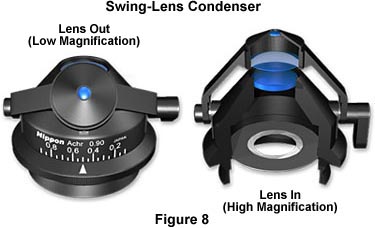
The conditions of Köhler illumination do not apply at magnifications using lower power objectives (5x and below). When preparing for low magnification microscopy, first align the microscope and adjust the optical pathway for proper Köhler illumination using the 10x objective. Most modern microscope condensers have a top lens that swings out of the light path for use with objectives of 5x magnification and below, as illustrated in Figure 8. Other condenser models have top lenses that can be unscrewed or have a rotating turret of condenser lenses for use with both low and high magnification objectives.
When the swing-out lens is removed from the optical pathway, condenser performance is radically changed and the aperture diaphragm no longer functions to control the numerical aperture of illuminating light rays. To avoid vignetting, the condenser aperture diaphragm should be opened to its widest setting, and specimen contrast is controlled with the field diaphragm, which now controls the numerical aperture of the illuminating light rays.
Contrast Adjustment at Low Magnifications
At low magnifications, the field diaphragm is used to control numerical aperture, specimen contrast, and overall image quality. Use this tutorial to explore the effects of field diaphragm opening size on these variables.
Start Tutorial »By properly adjusting the microscope for Köhler illumination, the specimen will be well-illuminated with even, glare-free light, giving good image resolution and contrast. For further information, consult our section on the theory of Köhler illumination and/or the basics of microscope illumination. Reference material concerning microscope illumination can also be found in our bibliography and in the section on web resources, which contains links to other microscopy web sites.