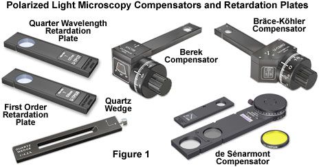
Introduction to Compensators and Retardation Plates
Polarized light microscopy is a valuable tool for revealing the presence and nature of submicroscopic structural motifs in a wide variety of materials ranging from mineral thin sections to fibers and biological specimens. In many cases, molecular ordering in these specimens is an intrinsic material property, but order can also be induced on multiple levels by dynamic shear, stretching, concentration changes, temperature fluctuations, and force fields. When the ordered state involves structural anisotropy, the optical state usually also displays anisotropic effects in polarized light observations. Quantitative measurements of optical anisotropy is therefore useful in the optical analysis of birefringent specimens.
Optical anisotropy is studied in the polarized light microscope with accessory plates that are divided into two primary categories: retardation plates that have a fixed optical path difference and compensators, which have variable optical path lengths. Addition of a retardation plate or compensator to the polarized light microscope produces a highly accurate analytical instrument that can be employed to determine the relative retardation (often symbolized by the Greek letter Γ) or optical path difference between the orthogonal wavefronts (termed ordinary and extraordinary) that are introduced into the optical system by specimen birefringence. The terms relative retardation, used extensively in polarized light microscopy, and optical path difference (Δ or OPD), are both formally defined as the relative phase shift between the orthogonal wavefronts, expressed in nanometers, according to the equation:
Δ = Γ = t • (ne - no)
where t refers to the thickness of the specimen (the physical distance traversed by light waves through the specimen), n(e) is the refractive index experienced by the extraordinary wavefront, and n(o) is the refractive index experienced by the ordinary wavefront. The terms (refractive index and thickness) on the right side of the equation are collective referred to as the specimen birefringence. From this relationship, it is obvious that specimens having differing thickness and refractive index gradients can display identical optical path differences or relative retardations. Furthermore, if either the birefringence or the thickness of a specimen is known, the other parameter can be easily determined.
Retardation plates are composed of optically anisotropic quartz, mica, and gypsum minerals ground to a precise thickness and mounted between two optical windows having flat (plane) faces, which are designed to introduce a fixed amount of retardation between the orthogonal wavefronts passing through the crystal. More recently, several manufacturers have shifted to the application of a highly aligned and stretched linear organic polymer to produce anisotropic retardation plates. Compensators and retardation plates have varying anisotropic plate thickness and optical properties targeted at producing a specific optical path length difference or relative retardation between mutually perpendicular (orthogonal) plane-polarized light waves when inserted diagonally in the microscope between crossed polarizers. In most cases the optical axis of the retardation material is confined to the surface plane of the anisotropic plate. Incident rays of linearly polarized light enter the plate perpendicular to the optical axis and are separated into orthogonal components that follow the same trajectory through the plate. However, due to refractive index differences introduced by the anisotropic retardation material, one of the wavefronts is shifted in phase (retarded) relative to the other. The wavefronts emerging from a retardation plate or compensator are polarized either in a linear fashion or with varying degrees of ellipticity, depending upon the degree of relative phase retardation.
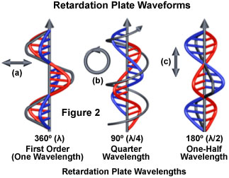
The three most common retardation plates produce optical path length differences of an entire wavelength (ranging between 530 and 570 nanometers), one-half wavelength (260-280 nanometers), or a quarter wavelength (137-150 nanometers). In addition, a variable optical path length can also be obtained by utilizing a tapering wedge-shaped design that covers a wide spectrum of wavelengths (up to six orders or about 3000 nanometers). The concept of a phase differential resulting from non-equivalent orthogonal wavefront propagation through retardation plates is illustrated in Figure 2. A wavefront passing through a full wave (one wavelength) retardation plate (Figure 2(a)) remains linearly polarized upon emerging and retains the same vibration plane. In contrast, the one-half wavelength plate (Figure 2(c)) rotates the plane of linearly polarized light by 90 degrees, while the quarter wavelength plate (Figure 2(b)) converts linearly polarized light into circularly polarized light (and vice versa). Retardation plates that introduce less than a quarter wavelength of phase shift produce elliptically polarized light.
A full wave plate is often referred to as a sensitive tint or first order red plate, because it produces the interference color having a tint similar to the first order red (magenta) color appearing in the Michel-Levy chart. Older first order compensators were fabricated by cleaving gypsum to the appropriate thickness to achieve the first-order red color, and may be marked gypsum plate, Gips, Gyps, One λ, or Δ = 530 nm on the retardation plate frame housing. If the plate originated in Germany, it will probably be labeled Rot I. The first order retardation plate is a standard accessory that is frequently utilized to determine the optical sign (positive or negative) of a birefringent specimen in polarized light microscopy.
Quarter wavelength retardation plates (sometimes referred to in the older literature as a mica plate) are usually fashioned from quartz or muscovite crystals sandwiched between two glass windows, in a manner similar to the first order retardation plates. Depending upon the manufacturer, quarter wavelength plates may be marked Mica, Glimmer, 1/4 λ, or Δ = 147 nm. First-order red and quarter wavelength plates are usually mounted in long rectangular frames that slide the plate through the compensator slot and into the optical pathway. Late model microscopes combine these plates into a single framework that has three openings: one for the first-order red plate, one for the quarter wavelength plate, and a central opening without a plate for use with linearly polarized light without compensators. In addition, these plate frames have knobs at each end that are larger than the slot dimensions to ensure the plates cannot be dropped, borrowed, or stolen.
An advanced class of retardation plates enables the operator to introduce variable amounts of phase shift in order to offset specimen birefringence. These devices, as discussed above, are termed compensators and are mounted in a frame that permits rotation or tilting of the anisotropic plate by a variable number of degrees. The quartz wedge is the simplest example of a compensator, and is utilized to vary the optical path length difference in order to match that of the specimen. Inserting the wedge into the microscope optical path increases the phase shift as the wedge thickness becomes greater. Another simple, yet elegant, compensation technique is termed the de Sénarmont method and employs a fixed quarter wavelength plate in combination with a rotating analyzer. Altering the transmission azimuth of the analyzer enables the de Sénarmont compensator to be used as a nulling device to negate the phase shift produced by the specimen through introduction of an equal, but opposite, phase shift. The angle of rotation required by the compensator to cancel specimen birefringence (producing extinction) is used to calculate the relative retardation or optical path length of the specimen.
Depending upon previous knowledge of the specimen, the relative retardation value can be used to determine whether specimen birefringence has a positive or negative sign, calculate the thickness, or actually measure the level of birefringence (the difference in refractive index experienced by the orthogonal wavefronts). From these observations, other important characteristics of the specimen can be elucidated, including the geometry and central motifs for molecular organization. For example, the tangential or radial orientation of polarizable bonds in the molecular structure of a spherical specimen can be ascertained by proper application of a retardation plate or compensator. However, even though retardation plates are useful for determining the geometry and sign of birefringence, it is the variable compensators that propel the polarized light microscope into the class of quantitative analytical instruments.
Practically all research-level polarized light microscopes are equipped with a slot in the body tube above the nosepiece and the objective rear focal plane, but beneath the analyzer. The purpose of this slot is to house a compensator or retardation plate in a specific orientation with respect to the polarizer and analyzer transmission axis vibration directions. Originally, the slot was oriented with its long axis directed Northeast-Southwest as observed from the eyepieces, but more recent microscopes have the direction changed to Southeast-Northwest. In older microscopes, the slot dimensions were 10 × 3 millimeters, but the size has now been standardized (DIN specification) to 20 × 6 millimeters. When the compensators and/or retardation plates are not inserted into the body tube, a cover is often fitted to prevent dust from entering the microscope through the slots.
A primary consideration when using compensators and retardation plates is to establish the direction of the slow axis vibration vector. By convention, this direction will be Northeast-Southwest and will be marked slow, z', or γ, but it is also possible that the slow axis will not be indicated anywhere on the frame. A convenient method of ascertaining the slow vibration axis of retardation plates or compensators is to employ the plate to observe birefringent crystals (such as urea) with a known optical sign in an orientation where the long axis of the crystal is parallel to the Northeast-Southwest direction of the retardation plate. If there is an addition to the optical path difference when the retardation plate is inserted (when the color moves up the Michel-Levy scale), then the slow vibration direction of the plate also travels parallel to the long axis. Alternatively, if there is a difference (subtraction) between the optical paths, then the slow axis of the retardation plate is perpendicular to the long axis of the framework.
Characteristics of Retardation Plates and Compensators
| Plate Type | Optical Path Difference(OPD - Nanometers) | Comments |
|---|---|---|
| Quarter Wavelength | 137-140 | Gray Interference TintCircular Polarization |
| One-Half Wavelength | 260-290 | Rotates Linearly Polarized Light |
| Full Wave (First Order) | 540-570 | First Order Magenta BackgroundBirefringence Sign Determination |
| Quartz Wedge | 0-3000 | Variable RetardationFour to Six Orders |
| Babinet | 0-3000 | Twin Opposed Quartz Wedges |
| Berek | 0-11,000 | Tilting Calcite PlateSeveral Ranges Available |
| Bräce-Köhler | 0-60 | Combination Mica Wedges Several Ranges Available |
| de Sénarmont | 0-540 (or 570) | Elliptical PolarizationRotating Analyzer |
| Elliptic | 0-540 (or 570) | Rotating Plate on Vertical Axis |
| Ehringhaus | 0-2800 | Twin Rotating Quartz Plates |
| Soleil | 0-3000 | Twin Quartz Wedges |
| Wright | 0-3000 | Combination Quartz Wedge |
Table 1
The most common retardation plates and compensators are the quarter wavelength, full wave, and quartz wedge plates. Other compensators that are available from various manufacturers are listed in Table 1, along with their optical path difference range and selected comments. The Babinet, Wright, and Soleil wedge compensators are variations on the standard quartz wedge plate. In the quartz wedge, the zero reading coincides with the thin end of the wedge, which is often lost when grinding the plate during manufacture. To overcome this difficulty, the Babinet compensator was designed with two quartz wedges superposed and having mutually perpendicular crystallographic axes. As a result, the zero order band is located at the center of the wedge where the path differences in the negative and positive wedges exactly compensate each other, to produce a full wavelength range on either side. In contrast, the Wright wedge is mounted over a parallel compensating plate composed of either quartz or gypsum, which reduces an optical path difference throughout the wedge equal to the parallel plate contribution.
Soleil compensators are a modified form of the Babinet design, consisting of a pair of quartz wedges and a parallel plate. Phase differences introduced through the compensator are controlled by changing the relative displacement of the wedges. The Bräce-Köhler compensator enables precise measurements of exceedingly small retardation values found in weakly birefringent organic specimens and low-strain glasses. The de Sénarmont and elliptic compensators take advantage of elliptical polarization, by employing a rotating analyzer (de Sénarmont) or with a quartz plate that rotates about a vertical axis (elliptic). The Berek compensator consists of a calcite plate cut normal to the optical axis that is tilted about the horizontal axis by means of a calibrated micrometer drum to enable precise measurements of retardation. Twin quartz plates are substituted for calcite in the Ehringhaus compensator, which operates in a manner similar to the Berek compensator. The Berek, de Sénarmont, and Ehringhaus compensators are standard tools for fiber analysis with polarized light microscopy.
Compensators and retardation plates are also commonly used for qualitative applications, such as control of background illumination or to improve the contrast and visibility in weakly birefringent specimens. In a properly adjusted polarized microscope (when the polarizer and analyzer transmission azimuths are exactly 90 degrees apart) the background appears very dark, almost completely black, and details from specimens that are very thin, or have low levels of birefringence, are often obscured. In many cases, the visibility and contrast in these specimens can be dramatically improved if a small amount of compensation (5 to 10 nanometers) is introduced with a compensator in order to increase the intensity of the background. Compensators can also be used to fine-tune the level of phase displacement between the orthogonal wavefronts (ordinary and extraordinary waves) with a target of increasing visibility and contrast of specimen detail. In short, birefringent specimens, particularly those displaying extremely low levels of phase displacement, are often imaged with superior contrast using a compensator than using a polarizer and analyzer alone.
Sorry, this page is not
available in your country.