An Introduction to the Gradient Contrast Method
1. Introduction
Since the invention of optical microscopes in the 16th century, light microscopes have contributed greatly to biological research including the discovery of microorganisms and red blood cells. In the 19th century, specimen staining technology developed, and transparent structures could be stained with color contrast agents to make them easier to see. Unfortunately, staining is toxic, which limits its use in live specimens. From the 20th century, various methods for seeing non-stained, transparent objects—such as phase contrast microscopy—were developed, becoming indispensable tools in biological research to this day.
2. Variation of Phase Contrast Methods
The common phase visualization methods for viewing transparent objects without staining are briefly explained with the respective optical element arrangements in Figure 1. Conventional phase visualization methods are realized by placing specific optical elements in the condenser pupil and the objective pupil, respectively.
The phase contrast method (Figure 1a) uses a combination of a dedicated condenser lens with a ring aperture and a dedicated objective lens containing a ring of phase film. Of the rays that pass through the ring aperture of the condenser, those that pass straight through the specimen pass through the phase film of the objective pupil. On the other hand, rays that are deflected by the specimen pass outside the phase film, producing a contrast of light and shade at the point where the two components interfere with each other. A characteristic feature of this process is that light blotches, called halos, appear at steps where the refractive index distribution changes in the specimen. Thick specimens are not suitable for this method because the halo appears too strongly.
The differential interference contrast method (Figure 1b) is a polarized shearing interferometer with complementary Wollaston prisms at the condenser pupil and the objective pupil positions. The specimen image becomes a double image slightly shifted in a fixed direction, and the refractive index step of the specimen is shadowed to make it appear three dimensional. Since polarization interference is used, observation is not possible if there is a plastic Petri dish or other object that causes polarized distortion in the optical path.
The modulation contrast method (Figure 1c) limits the illumination beam in one direction using the condenser pupil’s slit opening. Guiding the light beam makes the straight portion of light in the specimen appear gray, while the contrast of the refracted part will change according to the refraction direction thanks to the objective pupil’s modulator. By transmitting or shielding a portion of light, a three-dimensional image similar to the differential interference contrast method can be obtained. Since polarization is not used in the modulation contrast method, plastic containers like Petri dishes can be used. However, the resolution is slightly reduced with this method since limiting the direction of the illumination beam means a small illumination numerical aperture (NA).
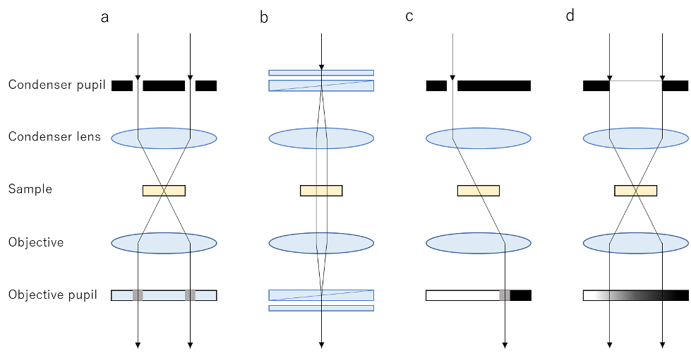
Figure 1. Optical arrangement of various phase visualization methods
The necessary optical elements of various phase visualization methods. a. Phase contrast method, b. Differential interference contract method, c. Modulation contrast method, d. Gradient contrast method.
3. Gradient Contrast Method
The gradient contrast method (Figure 1d) is characterized by generating a pseudo three-dimensional image similar to the differential interference contrast method. While other phase visualization methods require multiple optical components to generate contrast in unstained specimens, gradient contrast can be realized by simply inserting a gradient ND filter into the objective pupil.
Principle of the Gradient Contrast Method
The gradient ND filter inserted at the pupil position of the objective has monotonically decreasing transmittance in one direction. The aperture diameter of the condenser lens projected at the pupil position of the objective is reduced to some extent compared with the objective pupil diameter. Where the refractive index distribution of the sample is flat, the aperture image of the condenser lens is projected at the center position of the objective pupil and is subsequently affected by the transmittance near the center of the gradient ND filter (Figure 2a). When there is an inclination in the refractive index distribution of the sample, the aperture image of the condenser lens is shifted from the center of the gradient ND filter, so when the light beam refracts at the sample location the overall transmittance by the gradient ND filter changes (Figure 2b and c). Therefore, it is imaged at a brightness corresponding to the inclination of the refractive index of the sample, and the refractive index distribution of the sample looks three dimensional (Figure 2d).
The aperture of the condenser lens can be adjusted using the aperture stop. When it is relatively large, the brightness change due to the sample’s refractive index inclination may not be enough. Therefore, the image captured with the image sensor is emphasized and displayed in easy-to-see contrast.
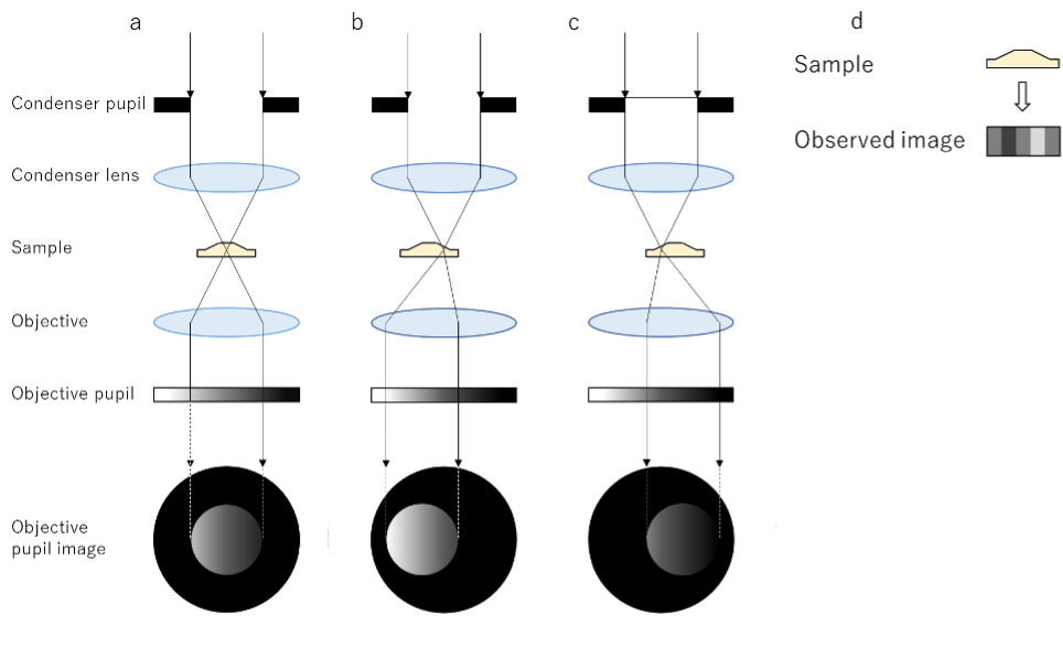
Figure 2. Illustration of the principle of the gradient contrast method
Description of the principle of contrast between light and shade on a phase object by the gradient contrast method. a. Where the phase distribution of the sample is flat, the light beam goes straight and passes near the center of the gradient ND filter. b, c. If the phase distribution of the sample is tilted, the light rays refract so that the direction of the inclination passes through either the brighter part of the gradient ND filter (b) or (c) through the darker part. d. The observation image is observed with a contrast of light and shade depending on the direction of inclination of the phase distribution of the specimen.
Gradient Contrast Method Features
The phase image produced by the gradient contrast method has many advantages over conventional phase visualization methods. The gradient contrast method can be applied to thick specimens because halos do not occur, unlike the phase contrast method. Since it is not polarization based, unlike the differential interference contrast method, the gradient contrast method can nicely generate pseudo three-dimensional images of specimens even through plastic vessels. Furthermore, since the NA of the illumination is larger than other methods, it is less susceptible to issues caused by imaging through the lid of a Petri dish with water droplets. This feature also prevents the deterioration of resolution caused by employing a shielding element in the modulation contrast method. Another practical advantage is that there is no need for a dedicated objective or switching elements at objective conversions, making observation faster and easier.
| Observation method | Phase contrast method | Differential interference contrast method | Modulation contrast method | Gradient contrast method |
|---|---|---|---|---|
| Thick specimens | Bad | Good | Good | Good |
| Can be used with a plastic Petri dish | Good | Bad | Good | Good |
| Can observe through a Petri dish with the lid on | Bad | Good | Bad | Good |
| Resolution | Good | Good | Passable | Good |
| Dedicated objective | Required | Required | Required | Not required |
| Switching condenser elements when converting objectives | Required | Required | Required | Not required |
| Cost | Low | High | Low | Low |
Table 1. A comparison of observation methods
Optical Configuration for the Gradient Contrast Method
The APX100 imaging system’s optical configuration is shown in Figure 3. Light is irradiated to the specimen through the optical path and imaged on the imaging surface.
A gradient ND filter is placed at a position that is conjugated with the objective’s pupil position. This filter enters the optical path only when the system is set for the gradient contrast method. The opening diameter of the condenser is automatically adjusted to the optimum value according to the magnification and pupil diameter of the objective.
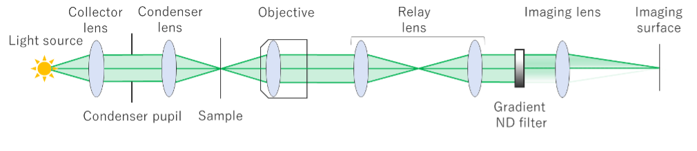
Figure 3. Optical configuration of the APEXVIEW™ APX100 benchtop fluorescence microscope for gradient contrast observation of unstained samples
Gradient Contrast Applications
Below, Hela cells in containers 1 and 2 were observed with a 10X objective, and images were captured using the four observation methods previously discussed so that the images could be compared.
- Glass bottom dish ※Plastic top lid is on
- 12-well microplate ※Water droplets adhere to the plastic lid on top
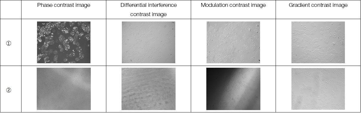
Comparison of results:
- The gradient contrast image is comparable to the phase contrast and modulation contrast images. In the differential interference contrast image, the polarization performance is reduced with the plastic lid, so the contrast is low.
- Compared to other observation methods, the gradient contrast image has a more even field of view and good contrast. The NA of the illumination is larger than other observation methods, and it is less affected by foreign matter on the specimen and water droplets in the container.
4. Summary
The gradient contrast method is a phase object observation method using a simple optical configuration that only requires the addition of a single, gradient ND filter to the objective pupil. It works well for observing transparent, living specimens without staining. Advantages of the gradient contrast method compared to the conventional phase object observation method include:
- It works well on thick specimens
- It is effective on specimens in a plastic Petri dish
- Observations can be made through a Petri dish’s lid, thus reducing the risk of contamination to cultured cells
- A dedicated objective is not required
- Element switching at objective conversion is not required
Authors
|
|
Shinichi Hayash, R&D, Advanced Optics & Biological Engineering, Advanced Optics 2, Evident
| |


Products Related to This Application
Sorry, this page is not
available in your country.